.gif) PY4SM
/ PY2DD / ZW4SM
PY4SM
/ PY2DD / ZW4SM
![]() Main
Page
- Marcus Martins / Minas Gerais / São Paulo /
BRASIL
Main
Page
- Marcus Martins / Minas Gerais / São Paulo /
BRASIL![]() Portuguese
Portuguese
Align correctly the antenna / Beam Headings
Locator Calculate (Grid-Locator) -
authoring PP5VX
If you are unsure, enter below the Latitude and Longitude
to your QTH to calculate your locator (GRID-LOCATOR) - after entering press
|
(The reproduction of the text below is authorized provided that the authorship is preserved and mentioned) - (All rights reserved-designed by PY4SM-PY2DD) PLEASE NOTE: The antenna is the most important equipment of a radio station!
An
antenna is an electrical device that converts electrical energy into
radio waves, and vice versa. It is generally used with a radio
transmitter or radio receiver. In the transmission, a radio
transmitter provides an oscillating electrical current in "radio
frequency" (i.e. high frequency alternating current (AC) at the
terminals of the antenna, and the antenna radiates the current
energy of electromagnetic waves (waves radio). In reception, an
antenna intercepts some of the energy of an electromagnetic wave in
order to produce a small voltage at its terminals, which is applied
to a receiver to be amplified. An antenna (radiating system) is just
an impedance transformer which couples the output of the transmitter
with the impedance of space, known as "ether” which is 377 ohms.
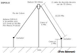
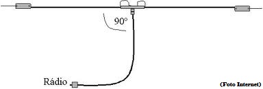
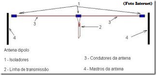
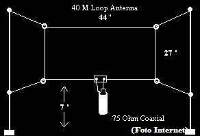
The antennas are essential components of any radio equipment (radio, broadcast television, two-way radio communication receivers, and radar, cellular phones, and satellite communications) as well as other devices such as garage door openers, without microphones wireless, Bluetooth-enabled devices, wireless computer networks, baby monitors and RFID tags on merchandise. Usually an antenna consists of an array of metallic conductors (elements), electrically connected (often through a transmission line) to the receiver or transmitter. The antennas can be designed to transmit and receive radio waves in all directions equally (omnidirectional antenna), or preferably in a particular direction (directional). In the latter case, an antenna may also include additional elements or surfaces without electrical connection to the transmitter or receiver, such as parasitic elements, parabolic reflectors, to divert radio waves into a beam or other desired radiation pattern. The first antennas were built in 1888 by German physicist Heinrich Hertz in his pioneering experiments to prove the existence of electromagnetic waves predicted by the theory of James Clerk Maxwell. He published his work in Annalen der Physik und Chemie ( 36 vol . , 1889). Many hams do not observe carefully the fact that the antenna is the most important equipment of any radio station and, although they have excellent equipment cannot good contacts nor good signal reports, it is the antenna that guarantees total irradiation transmitted signals. Is always a doubt, even for the more experienced, decide which antenna will operate. We believe that the more simple and efficient is without doubt the Dipole antenna. More dipoles antennas used are the "1/2 wave", i.e. those which have half the length of the track on which we operate. For example, an antenna for the 80 meter band will have approximately 40 meters in total length. An antenna for 40 meters tera 20 meters long. Dipole antennas can also be fitted in the position of an inverted V. The way to calculate the Dipole is extremely simple:
Antenna length =
142,5 If we want to build a dipole antenna for 40 meters band, we should define what is the frequency of "middle of the track". If the goal is to operate preferably in telegraphy (CW), the central frequency is 7,025 kHz, that's because the Telegraph range from 7,000 to 7,050 kHz. Just now replacing in formula (f = 7,025) and the result will be: 20.28 (twenty metres and thirty-six centimeters), i.e. 10.14 (ten meters and 14 inches) to each side of the antenna (leave about 10 inches, the more, in each side for easy adjustment.
DIPOLE and INVERTED V = > Calculate your antenna for frequencies below 30 MHz
The total length of the INVERTED
"V"
will be
meters.
Each side of the dipole en "V" inverted will be meters. Use common cable diameter 10, 12 or 14 AWG. Use good quality coaxial cable with impedance of 50 Ohm RG 58 type (fine) or RG-213 (thick) to feed the antenna (how many yards are needed to reach the transceiver). The time has come for adjustments that must be made with R.O.E meter (stationary were in), initially in the frequency of our example (7,025 Khz) where we should have the best income (falling gradually when we move away from 7,025 Khz, up or down). The adjustment should be made (if required) by reducing its length on both sides of 1 and 1 cm. Avoid cutting the cord, shorten the antenna and wrap the tips. After each reduction, make new measurement of R.O.E., (with a lot of patience) repeat as many times as you need, until the stationary were in reach at minimum. Need very careful not to turn on the transmitter when the cold stretch antenna being cut! Whenever possible, mount the antenna as high as possible in relation to the soil. Good QSOS and many DX 's.
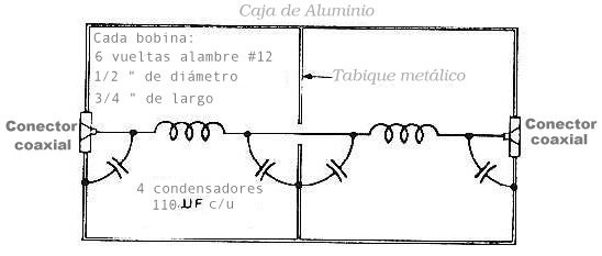
Build a filter and avoid interference in Televisions references (TVI) Schema for the construction of a simple but effective filter that effectively help to suppress the interference of RF armonics in television receivers.
The reproduction of the text above is authorized as long as the authorship is preserved and mentioned - All rights reserved designed by PY4SM - PY2DD
Antenna Basics and Theory
-- WOW -- See this One -- From Navy Training
Series
The
DxZone
has nearly 600
Antenna Articles Antennas A Bunch -- From Ham Radio Spectrum Dr. Ace's Antennas -- From WH2T -- Inverted L, Mini Super Loop, Full Wave Loop, Double Bazooka Coaxial Dipole, Homebrew 4:1 Balun -- Loaded with ideas -- dB, dBi, and dBd, -- Invisible and Hidden Antennas -- About SWRAntenna Application Notes -- Antenna and Feedline Measurements, Return Loss Bridge Basics, Duplexer Tuning using Bridge Antenna Design and Software From G4FGQ -- Loaded -- many antenna design programs, coax rating, ferrites and toroids, Groundwave propagation N4UJW Antenna Design Lab --- Loaded N0LX Antenna Page - Lots of Mobile Antennas W8JI Antenna Articles -- Receiving * Crossfire Phasing * Transmitting * Combiner and Splitters * Toroid Balun Winding * Balun and Transfomer Massive Antenna Page -- From "Your Remote S-Meter" Pages
AM
Loop Antennas
EH
Antenna Forum --
Yahoo
End-Fire Arrays
-- From Integrated publications Four Dollar All Band Antenna -- From Joe Tyburczy, WB1GFH Full Wave Loop Antenna 10M thru 80M -- From Western Canada's Ham Radio YL Site FVR Spitfire Array -- From The Yankee Clipper Contest Club G5RV Design and length Considerations -- From AA1LL Grounding Is Key To Good Reception -- From John Doty GRASSWIRE -- By K3MT Hair-Pin MonoPole -- A shorty From Wilfred Caron Half Square Antennas -- From K3KY Half Wave End Fed, No Radials Antenna -- From OE3MZC Halo Antenna 2M-- From N2KBK Halo Antenna 2M Square -- From N4UJW Halo Antenna 6M -- From W3DHJ HenTenna -- From The N4UJW Antenna Design Lab New HF Antenna From HB9ABX -- construction of small HF antennas to provide the same efficiency as large antennas. HF Antennas - Various -- From The ARRL HF- and VHF-Yagi-antennas - HomeBrew -- From DK7ZB Height Of Dipoles - Patterns By AA3RL Hexagonal Beam - via EI7BA MegaHex Beam 30/40 Meter -- From K7HC HT Extension Antenna - The Tiger Tail
IK-STIC --
multi-band vertical dipole antenna used for quick set-up and quick band
change -- From W2IK
J-Poles -- From
The ARRL Liquid Antennas -- Not April 1 stuff Log Periodic Antenna Calculator Full Wave Loop Antenna 10M thru 80M -- From Western Canada's Ham Radio YL Site Loops -- From The ARRL Loop Antennas -- Plans for each Amateur Band Loop Antenna Forum -- Yahoo -- Needs subscribing but lots of info here Low Band Antennas -- From K3KY Mac Antenna Master Software Magnetic Loops for HF -- From W2BRI HF Magnetic Loop Antennas -- By Glenn C Sperry, KI6GD Magnetic Loops -- By Wolfgang DJ3TZ Magnetic Loop Antenna -- From HB9ABX Magnetic Loop Design -- From QRZ Magnetic Loop Antenna's Magnetic Loop Antenna 10-30 Mhz -- From Matthew G0VBC Microwave Antenna HandBook -- From W1GHZ Mobile Antennas -- From The ARRL Mobile Dual Band VHF/UHF Antenna -- Homebrew Project from VE3RGW Mobile HF Antenna By HB9ABX 10-80m MOBILE HF MULTIBAND ANTENNA PROJECT - From Mark D. Lowell, N1LO Moxon Antenna Projects -- 17M and 20M Via KD6WD
NVIS I- Near
Vertical Incident Skywave Antennas -- By Patricia Gibbons - WA6UBE
Parabolic
Discone Petlowany Three-Band Burner Antenna -- Short vertical antenna - Resonant on 20, 15 and 10 meters, without traps, 12 and 17M with a tuner. Phasing Arrays - Vertical Antennas -- From Butternut Portable Antennas -- From The Ham Club At University of Hawaii at Manoa Portable Antennas -- From HFPack Portable dual-band antenna for 20 and 10 meters. - The Flower Pot Antenna from IZØFYL QRZ Shareware Collection antennas -- over 40 antenna files Quad Antenna Calculator -- From KD6DKS Quads By EI7BA Quad Antennas --- From The ARRL Quad - Multiband - By EI7BA Rhombic Antennas 30M - 6M -- From KC0FVV Rhombic Antennas -- From Integrated publications Rhombic Antennas -- From Ian Cummings Feedback Rhombic -- -- From Ross W1HBQ Roof Top Tower -- By KB0YKI Rotary Dipole For 17 And 20 Rubber Duck Antennas
Satellite Antennas
T2FD Antenna
Vee Antennas --
From Integrated publications
Vertical Antennas
-- From The ARRL
Double Extended Zepp Dipole -- Cut for 15 Meters 160M/80M Coaxial Receiving Loops -- By KC2TX Balloon and Kite Antennas On The Top Band -- From G4VGO Battle Creek Special -- Info From PI4CC Contest Club KE4UYP Top-Fed 1/4 Wave Linear Loaded Vertical For 160M K5OE Antennas -- HF Antennas 40/80/160 55 ft Vertical Low Band Antenna -- From K3KY Verkürzte Antennen -- Short Dipoles and Verticals for 160m & 80m -- From DJ9RB Skywire Loop Antenna -- From The ARRL Antenna Projects From The YCCC -- Double-L For 80/160, Two Wire Beverage, A Poor Man's 160 Meter 4-Square, Using a 4 square Vertical Verkürzte Antennen -- Short Dipoles and Verticals for 160m & 80m -- From DJ9RB 160/80/40 Meters - 55-Foot Vertical From K5OE VE3GK's Homebrew Site -- 80M Rotating 2 element Quad Verkürzte Antennen -- Short Dipoles and Verticals for 160m & 80m -- From DJ9RB Wire Antenna for 75 and 80 Meters -- From Ross W1HBQ 40M/80M Trap Dipole -- From QRZ 80/40 Meter Vertical From EI7BA 80 Metre Slinky Dipole For QRP - From M0WYM 80 Meter Inverted Vee From GERRY VE3GK 80 Meter Antenna -- Reduced Size For Small Lots 2 EL SHORT BOOM 80M YAGI From VE6WZ. Short Dipole for 80M -- From 4S7NR 80 Meter Frame Antenna -- From Harry Lythall - SM0VPO Full Wave Loop Antenna 10M thru 80M -- From Western Canada's Ham Radio YL Site KE4UYP Top-Fed 1/4 Wave Linear Loaded Vertical For 80M KE4UYP RSBVE (Reduced Size Broad Elevation Verticals) For 80M KE4UYP Top-Fed 3/4 Wave Linear Loaded Vertical For 80M KE4UYP RSBVE (Reduced Size Broad Elevation Verticals) For 60M Verticals 40M Shortened Loop -- By Ben Smith, W4KSY Via Antennex NVIS Roost Emergency Antenna Kit By Bob W2IK WB0NNI 40 Meter Linear Loaded Vertical K5OE Antennas -- HF Antennas 40/80/160 55 ft Vertical St. Louis Vertical -- By Dave Gauding, NF0R DDRR - for 40M -- Directional Discontinuity Ring Radiator Antenna 40M Triangular Full-Wave Vertical Loop Antenna -- From W5DXP 40M/80M Trap Dipole -- From QRZ 40 Meter Delta Loop By PY4VE Via K4TX ShortyForty Dipole -- By W5VM Via K7MEM ShortyForty Dipole -- From FlashWebHost Sterba Curtain 40M -- from KB8PGW G5RV 40m Beam Antenna -- From W5DXP 40m Vertical Antenna for $10 -- From KG6IIR End fed 20/30 Meter Antenna -- From W0VLZ 20M 3 Element Monobander -- From The ARRL K5OE Antennas -- HF Antennas - 10/15/20 m Dipoles VE3GK's Homebrew Site -- 7Element 20M Yagi 63ft Boom 20M Yagi Optimized Wideband Antenna 20M Delta Loop Moxon Antenna Projects -- 17M and 20M Via KD6WD 17M Beam Antennas -- From The ARRL Moxon Antenna Projects -- 17M and 20M Via KD6WD 15 Meter Beam -- From The ARRL K5OE Antennas -- HF Antennas - 10/15/20 m Dipoles 15M Delta Loop 15M Yagi Optimized Wideband Antenna A One Element V Beam For 15 M From KB4XJ 12M Beam Antennas -- From The ARRL Two element 10-Meter beam -- From The ARRL 10M Yagis a Bunch -- From The Antenna Elmer 10M Yagi Optimized Wideband Antenna No-Tuner, All-HF-Band, Horizontal, Center-Fed Antenna -- From W5DXP 5 Band Log Periodic Dipole Array -- From VE7CA 6-Band HF Center-Loaded Off-Center-Fed Dipole - From Serge, ON4AA 7-Band Semi-Vertical Trap Antenna - From Bob Rice, VE3HKY 12- and 17-meter lightweight Yagi -- From The ARRL All-band Wire Antenna - From Joe Tyburczy, WB1GFH MULTIBAND HF DIPOLE PROJECT Pyramidal Antenna for 14-30 MHz -- From Ross W1HBQ One Element Beam 20 Thru 6 Eight Bands On One Coax - The Windom Antenna -- From KH2D CobWeb Antennas -- 5 Band From G3PJE Double-L Antenna For 80/160 -- Via The YCCC Full Wave Loop Antenna 10M thru 80M G5RV Multi-Band Antenna by Louis Varney Hex Beam 20 thru 10M -- From K4KIO IK-STIC -- multi-band vertical dipole antenna used for quick set-up and quick band change -- From W2IK IK-STIC 2 vertical, all band, antenna, 25 feet tall, under 5 pounds! With a tuner covers the amateur radio HF bands from 40 - 10 Meters.
10-80m MOBILE HF MULTIBAND
ANTENNA PROJECT - From Mark D. Lowell, N1LO
Pedestrian 5-Band Mobile Antenna
- From W3FF
Tri-Band 2 Element Portable Yagi
-- From
Markus Hansen, VE7CA 5/8 Six Meter Vertical -- by G3JVL 50 Mhz Antennas By ON4ANT Six Meter Antennas A Bunch -- From The UKSMG News Six Meter J-Pole -- By K4ABT Super J-Pole Antenna (Collinear Design) - By KB0YKI Six Meter Halo -- From Steve KB1DIG Six Meter Halo -- From W3DHJ Six Metre Portable Dipole For QRP - From M0WYM Six Meter Hex Beam -- three elements with a turning radius of 54 inches Six Meter Sloop By K0FF Six Metre Long-wire Aerial -- By Brian D. Williams, GW0GHF Six Metre Indoor Loop -- By Colen Harlow, G8BTK Six Metre Antenna -- By Maurius - ZR6YY Six Meter Long Wire Antenna - From GW0GHF Long-wire Aerial for Six Metres By Brian D. Williams, GW0GHF 6M and 2M Yagi -- From The Antenna Elmer 6M Yagis a Bunch -- From The Antenna Elmer Six Meter Yagi -- From The ARRL Six Meter three-element Yagi -- From The ARRL Six Meter Tri-Yagi -- From The ARRL Six Meter Monster Beam -- 8 element, 41 foot boom, 14.0 dBi gain, By N6CA Optimised Six-Metre Yagi by Brian Beezley, K6STI Two portable 6 meters antennas - two-element quad and a three-element yagi with telescoping elements -- From VE7CA 2M/440 MHz Dual Band Copper J-Pole From N7QVC 2M Fan Antenna (Yes From an Electrical fan) 2 M 1/2-Wave J-Pole -- VHF-FM (Stealth) Antenna Made From 450-Ohm Ladder Line -- From KB1GTR & KB1DIG 2M Self Supporting J-Pole for Emergency Use -- From Bob Hejl W2IK 2M Log-Periodic Dipole Array -- From The ARRL 2m 8db collinear for portable use.From M3FVB 2 METER SSB SQUARE LOOP From N4UJW 2m Quagi By W5UN 2M Yagis a Bunch -- From The Antenna Elmer 2M Quadix -- from Ross W1HBQ 2m 8db collinear for portable use.M3FVB 3 element 2-meter Yagi -- From The ARRL 5 element 2-meter Yagi -- From The ARRL 2M 9 Element Yagi 5/8-WAVE COLINEAR "OUTSIDE PVC" 2-METER 146 MHz FM J-POLE Via KB1DIG & KB1GTR 6dB COLINEAR VHF ANTENNA -- From Harry Lythall - SM0VPO BiQuad For 2m/440 - FROM KE4UYP Building A 2-meter J-Pole Antenna By Jaden Cheap Yagi Antennas for VHF/UHF -- From Kent WA5VJB The Simplest Collinear -- From Ross W1HBQ Cycloid Collinear, a CP Omni for 2M from Ross W1HBQ Desk Buddy 2M Antenna - From Bob W2IK DDRR - for 2M -- Directional Discontinuity Ring Radiator Antenna Grid Yagi -- From Ross W1HBQ Halo Antenna 2M-- From N2KBK Halo Antenna 2M Square -- From N4UJW HO Collinear, a Horizontal Omni for 2M from Ross W1HBQ PacketRadio Operator's Antenna Handbook -- Antenna Basics, 2M & 6M Antennas SlimJim 2M Antenna Sperrtof 2M Antenna -- aka Sleeve Dipole or Sleeve J-Pole. By ON4CFC Via Antennex Super J-Pole Antenna (Collinear Design) - By KB0YKI VHF/UHF Antennas -- By KB0YKI -- J-Poles, Super J-Pole, Omnidirectional, Quads, Yagis VHF EggBeater Antenna - From ON6WG / F5VIF Quick and Simple 2 Meter Ground Plane Project Via HamUniverse W2IK Quick Stik Emergency Field Antenna For VHF/UHF -- stored in a PVC sewer tube (which also acts as it's lower base) Cheap Yagi Antennas for VHF/UHF -- From Kent WA5VJB 220 MHz Quickie Quarter Wave Antenna -- From Artsci 220 MHz J Pole Antenna -- From N6ZAV Super J-Pole Antenna (Collinear Design) - By KB0YKI Cheap Yagi Antennas for VHF/UHF -- From Kent WA5VJB Coaxial Collinear Antenna -- 432 MHz -- From Via N9ZIA Small 70cm Yagi -- From The ARRL 9 dB, 70cm, Collinear Antenna From Coax -- Version I -- From N1HFX 2M/440 MHz Dual Band Copper J-Pole From N7QVC 432 8 Element Quagi Antenna By N2KBK 440 MHz -- 2 Element & 4 Element Yagi's - From The Antenna Elmer Super J-Pole Antenna (Collinear Design) - By KB0YKI UHF EggBeater Antenna - From ON6WG / F5VIF 432MHz 8 Element Quagi Antenna -- By IK1HGE Cheap Yagi Antennas for VHF/UHF -- From Kent WA5VJB Cheap Yagi Antennas for VHF/UHF -- From Kent WA5VJB Microwave Antennas and Greg's Wireless Networking Info Page Curtain Quad for 1296MHz -- From Ross W1HBQ Curtain Quad for 2.4 GHz -- From Ross W1HBQ 2.4GHz Omni Antenna 2.4 GHz Sardine Can Antenna -- A Double Quad Bow Tie Shortened 3D Corner Reflector Antenna - For 2.4 GHz - From Dragoslav Dobri YU1AW CC&R INFO
HOMEBREW STEALTH ANTENNAS
Balcony Antenna
-- From Harry Lythall - SM0VPO CliffDweller II antenna End-Fedz -- full length half wave dipoles, but with an important difference. The coax connector is at one end of the dipole, where it is most needed. From Universal Radio EZ HANG -- SlingShot & Reel Device for installing wire antennas Force 12- 9 Foot Vertical Force 12 Aluminum Flag Poles & Antennas HamSticks MFJ Apartment Antenna 40 Meters to 2 Meters MFJ-1622 MFJ Super Loop Antennas MFJ ScrewDriver Antennas Quicksilver Radio Products MinuteMan™ HF Portable Antennas Stealth Antennas -- HF Mobile Antennas By VE7BOC Texas BugCatcher - GLA Antennas Texas Twister - GLA Antennas Ventennas -- The Forbes Group Ventanna HFP-2 10 Foot HF Antenna -- 6.5 to 30 MHz !!! Vern Wright's HF Mobile Antennas, MP1
|
|||||||||||||||||||||||||||||||||||||||||||||||||||||||||||||||||||||||||||||||||||||||||||||||||||||||||||||||||||||||||||||||||||||||||||||||||||||||||||||||||||||||||||||||||||||||||||||||||||||||||||||||||||||||||||||||||||||||||||||||||||||||||||||||||||||||||||||||||||||||||||||||||||||||||||||||||||||||||||||||||||||||||||||||||||||||||||||||||||||||||||||||||||||||||||||||||||||||||||||||||||||||||||||||||||||||||||||||||||||||||||||||||||||||||||||||||||||||||||||||||||||||||||||||||||||||||||||||||||||||||||||||||||||||||||||||||||||||||||||||||||||||||||||||||||||||||||||||||||||||||||||||||||||||||||||||||||||||||||||||||||||||||||||||||||||||||||||||||||||||||||||||||||||||||||||||||||||||||||||||||||||||||||||||||||||||||||||||||||||||||||||||||||||||||||||||||||||||||||||||||||||||||||||||||||||||||||||||||||||||||||||||||||||||||||||||||||||||||||||||||||||||||||||||||||||||||||||||||||||||||||||||||||||||||||||||||||||||||||||||||||||||||||||||||||||||||||||||||||||||