Home Brew dual band antenna
Basic design theory
This antenna is just a 1/4 wavelength resonator for both UHF and VHF band. It provides no GAIN as compared to other multi-section design. Yet it has the advantage of better stability against surrounding influence (e.g. different mounting method, unexpected reflection by surrounding objects, difference in stray capacitance between test bench and operating field ). The antenna consists of two sections. The lower section is a conductor cut to resonant on UHF band. The upper section is a coil which serves two purposes. For UHF band, this coil is a RFC (radio frequency choke). It blocks UHF frequency energy to flow through upper section. For VHF band, this coil enhances the inductance provided by lower section. The resultant inductor, together with surrounding stray capacitance will form a VHF resonant circuit and becomes the VHF antenna. To get a better understanding on the tune up procedure, it will be helpful to review some basic rules onantennas.
- Antennas are LC circuits. The LC components control their resonant (operating) frequency. Inductive component is formed by metal conductor of the antenna's body while capacitive component refers to stray capacitance between the antenna body and its surrounding grounded conductor.
- Increasing either L or C component can lower the resonant frequency while reducing them causes the opposite effect. Inductor can be increased by adding physical length of the antenna element or by making it as a coiled structure. Capacitance can be increased by using a larger surface area on the antenna body, by adding capacitor hat or by reducing physical clearance between inductive section from ground. In this issue, we mainly alter the inductive section of the antenna to achieve tuning. That is done by cutting length of the conductor and by changing length of coil structure.
Mechanical structure and material consideration
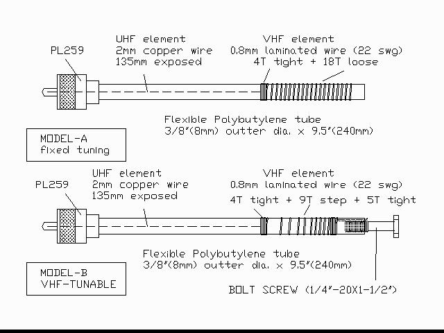
Fig.1 shows two possible structure of this antenna. Model(A) being the fixed style and model(B) being VHF adjustable. The lowest section of the antenna is a PL-259 plug. The center pin of which is soldered to a 2mm diameter copper rod. I got this copper rod from core conductor of RG-8U coaxial cable. It should create an exposed section (clear off from metal shield of the PL-259 plug) of about 135 mm. More detail will be discussed in tune-up section. This copper rod is hidden inside a tube which acts as the coil-form for the upper section. To avoid absorption of RF energy emitted from the antenna, material of this tube must be carefully selected. I used PVC faucet tube for this part. They are polybutylene - those gray color PVC plastic which is cheap and easily obtainable from most hardware stores. You can use any other tubes provided their external diameter can fit into the barrel of the PL-259 plug plus it does not absorb radio waves. We can use a microwave oven to check out if a certain material will absorb R.F. energy. Material placed inside an operating microwave oven will generate heat if they absorb radio waves. Place the material under test inside the microwave oven together with a cup of water (for safety). Execute heating process for say 1-2 minute and check surface temperature of the object under test. If the material stays cool as compared to the cup of water, we can assume that it do not favors radio wave absorption and will be suitable for the job. A small hole (1 mm) is drilled on the tube just besides tip of the UHF section. A piece of laminated copper wire (22 swg) is soldered to the tip of the UHF section and is leaded to outside of the tube through this hole. The rest of this wire is wound on the upper part of the tube and forms the VHF section. After proper tuning is completed, the whole antenna is sealed within a piece of heat shrink coating down to the neck of the PL-259 plug. A rubber cap can be placed on top of the antenna in order to prevent water from entering inside of tube.
Constructing procedure and tune up
Cut out a piece of 2 mm copper rod. Let's starts with a length of about 160 mm. That should cover future cutting job and the length hidden inside the PL-259 barrel which is not counted for radio emission. Insert it into the center pin of the PL-259 plug and make a smooth soldering at the tip of the pin. We now have a UHF antenna. Before attempting to tune it, prepare two pieces of 2 mm copper rods also, they should be of length 140 mm and 500 mm respectively. They will serve as the temporary ground planes for UHF and VHF test. By using a reflectometer (SWR meter), check out the reflect power from this simple antenna when UHF power is fed. Cut the length of this section slowly (in 2-3 mm step) and observe changes on reflect power at lower end of target frequency band. Without attachment of a good ground plane, it is impossible to obtain zero reflect status so just go for the lowest possible value. Using the low end frequency for testing is a safety precaution. That prevents you from over cutting the antenna without notice. After you felt satisfied with the cutting progress and has slightly over cut the rod ( reflect power increase again upon further cutting ). Change test frequency to middle of operating band and proceed further cutting with high care. Once reflect power increased again (indicating slight over cut), pick up the earlier prepared 140 mm section and touch it to the PL-259 plug of this antenna. You should see the reflect immediately drops for a lower or even 1:1 value. This confirms that the section is properly cut and is ready. Cut out a piece of faucet tube (240 mm in length). Insert it into the barrel of the PL-259 plug. Make a mark on the tube where it just clear out from the PL-259 barrel. Remove the tube and put it side by side with the UHF antenna while the mark is aligned with the top of the PL-259 plug. Make another level mark for the tip position of the UHF section. Drill a 1 mm hole on the tube at that mark. Prepare for a piece of 1 meter long 22 swg laminated wire . Push it through the above mentioned hole and force it to run through the lower section of the tube until it made its way out from the bottom. Solder this wire to the tip of the UHF section and pull the wire back into the tube. That will bring the UHF section into the tube as well. Pull out any excess wire inside the tube until the tube is seated tightly inside the PL-259 barrel again. Wind the laminated wire on the tube for 22 turns. These turns should be in a pattern as shown in fig.1. The first 4 turns which forms the RFC for UHF band must be tight. The later 18T should be interleaved and evenly spread along until reaching end of the tube. That should make a coil of approximately 80-90 mm in length. Place the antenna on the reflectometer again, recheck the SWR or reflect status on UHF band, there should be no change as compared to earlier test result. Change frequency to lower end of target VHF band and repeat the test. Tune the VHF response of the antenna by altering length and pitch of the 18T section. Generally speaking, start with evenly distributed pitch and try to control the resonant frequency with coil length. If that cannot work out, try to rearrange the pitch unevenly - tighter pitch near the bottom and looser pitch near the top. Such treatment can further lower the operating frequency. Like tuning job in UHF band, go for the lowest possible reflect on the middle spot of your target band and confirm proper tuning by adding of VHF ground plane (500 mm long copper rod). Once both bands are confirmed in tune, seal and secure the whole antenna with heat shrink tube. The antenna is now ready for application at mobile vehicle environment. If you want future tuning possible in order to match different field environment, you can try model(B), the VHF tunable configuration. In that case, another 1 mm hole should be drilled on the tube near top portion of the coil. The 22 swg wire should be leaded back into the inner side of the tube. A section of contact wire 10 mm in length at top end of tube should be formed. A 1/4" metal bolt is screwed in to fill up the tube. Its pitch should bite through the laminated surface of that 22 swg wire and make a contact with the wire. The bolt will become an extension of the coil and by adjusting the bolt length (in/out or even changing length of bolt), the VHF resonant point can be adjusted.
Conversion for base station application
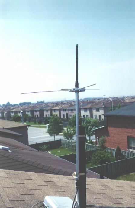
This antenna can be used at base station configuration also. The trick is to provide sufficient ground plane system in order to form those essential stray capacitance for proper tuning. Fig.3 shows a simple dual-band ground-plane design and corresponding mounting for base station.
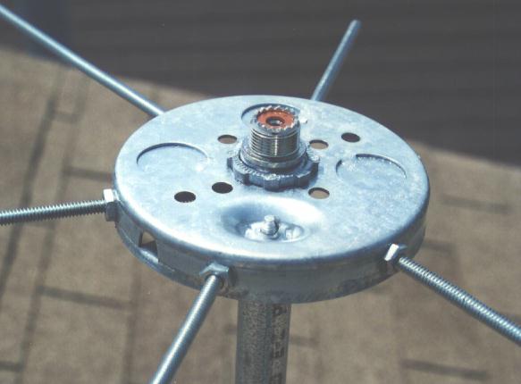
This mount can be used with other UHF/VHF mobile antenna design also ( as long as they use PL-259 base connector ). It is a very good test bench if you have needs to compare efficiency between two mobile antennas or just want to convert another mobile dual band antenna for base station application. The materials for this mount are all easily obtainable pipes and sockets used in electric power installation. We need a piece of electric conduit (metal pipe for protection of electric cable). Length is not critical, say 20" will be fine. It should be of the 0.5" diameter series. These pipe are measured for their inner diameter. Find also the EMT connector (set screw type) for the same family and put them on both ends of the conduit. The reason for using this dimension is because - the inner diameter of such EMT connector will perfectly fit a SO-239 socket (UHF female bulkhead receptacle solder type). You can tap threads on the inner wall of the EMT connector so that the SO-239 can be screwed in. I used a short cut, just hammer the SO-239 into the connector. The only weakness of this method is - the socket cannot be removed easily or frequently. Anything must be done right at the first move and cannot be repeated for correction. By putting two SO-239 socket on each end of the conduit and have them connected inside the pipe, a female to female adapter is formed. The upper socket is for mounting of the antenna, the lower one is for connection of feed line. The length of the conduit serves another purpose - made possible mounting of the whole antenna on another vertical pole easily with two hose-cramps. We also need a piece of 4" round-pan ( top cover for those circular shape power junction box ). It provides a flat platform where the ground-plane elements can be mounted. The ground-plane elements are made of threaded stainless steel rods (size 10-24). Holes at 60 degree separation are drilled on the vertical edge of this round-pan. The threaded rods can then be mounted through these holes with two nuts (inside and outside the round-pan's edge). Length of ground-plane elements control their resonance frequencies. Different materials needs different lengths to achieve resonance. Our earlier mentioned value 135mm at UHF and 500mm at VHF are only good for copper conductor. For steel, the length will be different. Togerther with situation that these rods are mounted 2" away from the RF socket, their dimension will be much shorter. Practicle test indicated that UHF ground elements in this design is best at length 70mm while VHF elements at 350mm. This length refers to rod's length between their tips and mounting point at round-pan. Since these rods are mounted with two nuts, their effective length can be adjusted. To play safely, the rods should be cut with 30mm extra length. That comes out as 100mm for UHF and 380mm for VHF. Adjusting procedure on their final length will be discussed later. The SO-239 connectors has to be connected inside the conduit. I made a mistake at the beginning. Feeling that both sockets are tightly hammered and in good contact with the pipe, their ground points should have been connected nicely. I used only single core wire to connect their center pin rather then using coaxial cable to join them. But I forgot one thing, the two EMT connectors were secured on the metal pipe with only two set screws ! That is not a good contact for radio waves. I was surprised by the test result of such prototype - SWR reading of nearly 1.8:1 even with proper 50 ohm dummy load teminated. After modifying the connection back with standard RG-58AU cable, SWR for this section normalized to 1:1. Drill six holes on the edge of the 4" round-pan and punch out the center hole on the top surface. Mount the round-pan on the upper EMT connector, Secure it with the nut which comes with the connector. Cut threaded rods to proper length ( three at 100mm, three at 380mm) and have them mounted on round-pan in alternate pattern. One UHF element followed by a VHF element then vice versa.
Construction of the mount is now almost finished ( awaiting final tune up ). It is not a bad idea to paint the whole thing - for protection against water damage in future. Try to do it after all ground-rods are set. We need good metal contact surface between the round-pan and the rods. Tuning of ground-rods are similar to tuning of main element. The longer the length, the lower the resonance frequency. Since we have three rods for each band, we can set one rod on the lower frequency limit, one on high limit and one for the center spot. This will create a flatter responce of the antenna in the entire operating spectrum. Always remember to work on one rod at a time (with the other five removed ). Set up one test frequency and alter the rod's lenght for minimum reflected power. Then mark the length and change for another rod with another test frequency. Put them back onto the round-pan with proper tested length after all key spots ( three for VHF and three for UHF ) are checked out. Reflection from near by objects can distort the above measuring result. These tests must therefore be done in open space, try to obtain clearance of at least 5 meter from any objects which might cause reflection. Always try to use high quality feed-lines to avoid creation of fake image of low reflection when reflected power are absorbed.
More detail on this antenna can be found in Radio Fun May 1994.