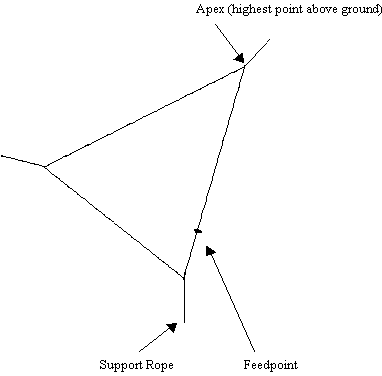
The Delta Loop's feedpoint is located near one of the bottom corners
providing a slight increase in gain and easy access when maintenance is
required.
Directional Characteristics
The radiating element or wire position in relation to the ground
determines polarization. If the wire is parallel to the ground, it
radiates horizontally. If the wire is perpendicular to the ground, it
radiates a vertical wave. If the wire is slanted, it radiates waves,
which have both horizontal and vertical qualities.
Calculating Length Of Wire Needed For 80 M Loop
Length (ft.) =
1005
--------------------------------------------
f (MHz)
Therefore, length of wire needed for an 80M loop antenna is:
Length (ft.) =
1005 =
272 feet
--------------------------------------------
3.7MHz
Materials Needed For Antenna
- Copper Stranded Wire #12
- 4 ceeramic or glass insulators (apex, two corners, and at
feedpoint)
- RG58 or mini RG8 Coax (50 ohm) Calculate length from feed line to
radio room plus a little extra.
- PL259 Connector (UHF male) - for end of coax which connects to
radio.
- Support rope for corners and apex.
- Roll of coax seal to wrap.
- Polyester braided rope (3/8") needed for halyard and support
ropes.
Step By Step Instructions
-
Draw to scale diagram of antenna and all supports with dimensions
on lot.
- Measure and cut wire length for antenna allowing 1' extra for
securing insulators. Careful not to bend wire.
- Lay the wire on the ground so that the sides can be measured and
the insulators fixed to the apex and corners. To fix insulator cut a
short piece of wire and twist it around the antenna wire for about
4" on one side and then cross over insulator end and repeat
4" up the other wire. This adds strength to the corners and
apex ands keeps insulators in place when raising antenna.
- Cut three pieces of support rope to clear and free antenna corners
and apex from trees/buildings, etc. Connect ropes to the three
insulators.
- Feedpoint connection � wavelength from bottom corner. (See
diagram) With a sharp knife, carefully strip back (not cut) 3"
of the exterior black jacket from one end of the 50 ohm coax being
careful not to score the braid underneath. Pull the braid gently a
part in one place and pull out the inner dielectric containing the
center conductor. The coax is now split in two. Expose the center
conductor by carefully cutting off 1" of the inner dielectric
which is covering the center conductor.
- Each wire end is then threaded through the closest insulator hole
and then tightly twisted around antenna wire on that end. This is
also repeated on the other end of the same insulator using the other
antenna wire. Wrap prepared coax end around the middle of the
insulator and secure with a clamp.
- Once this is done and the materials have been cleaned well, solder
one of the #12 gauge copper wires to braid and the other to the
center conductor. To avoid water and contamination in the feed line,
the antenna end of the feed line must be adequately covered with
coax seal . Remember, the feed line connection at the center
insulator should not be done until after the antenna wire has been
tied securely to the insulator.
- Construct a 1:1 broadband balun. Wind or coil a length of coaxial
feed line for 6-8 turns near point of connection and secure with
electrical tape. Lengths are not critical. Diameter of coils
approximately 8".
- Pull the antenna wire carefully up in the air by pulling down on
the rope end which will eventually be tied to the limb of the tree.
Once desired height of highest corner or apex has been reached, tie
rope to limb near ground and within reach by a ladder.
- One of the two remaining insulators will have its rope now tied to
the second tree (or other support) which also has a collar but no
pulley. This insulator and the previous one are counterweighted
(halyard) and allowed to move freely.
- The delta loop is now ready to be raised using the pulley on the
halyard at the top of the tree or pole. Once the apex is fastened at
the correct height proceed to fasten securely the corner ropes to
their tie supports.
- Install the PL259 (UHF male) Connector on end of coax feedline in
radio room. An adapter is available if using the smaller RG-58 size
coax. Connect to transceiver and test for SWR.
Introduces slack so that during high wind conditions the wire loop
can move, thus reducing stress on wire avoiding breakage. See directions
for making halyard.
-
Bucket (with several holes on bottom) with handle plus
counterweight weighted with bricks or sand and rocks.
- One pulley large enough for line to run through freely keeping in
mind that rope can swell when wet. Buy a fast-eyed brass or bronze
marine type pulley.
- Polyester braided rope (3/8") needed to go up and down full
length of tree trunk from collar to ground. Allow for extra to tie
around lower limb and to raise antenna without running out of rope.
- Make a trunk collar to protect bark of tree. This is done by
threading a short piece of rope through an old hose or other soft
tubing, the diameter of the trunk, where the collar will be
positioned up high on the tree. Thread the pulley onto collar rope
where the two ends of collar will meet together and tie securely.
Only an experienced tree climber, with safety climbing equipment,
should do the climbing.
- While climber is up on the tree have him take one end of the long
rope and feed it through the pulley. As he comes down he can pull
that end down with him to ground level. Do not cut rope yet until
after the antenna has been raised up, otherwise you may find
yourself with too short a rope.
- One end of rope will be tied to the weighted bucket handle and the
other end tied tightly to a low limb within your reach. Bucket
should be suspended about six feet from ground floating freely. The
antenna wire at this point is still lying on the ground.
- Just before the antenna wire is ready to be raised, tie the
appropriate support short rope to the insulator at the apex of the
antenna to the halyard rope's mid-point. This rope enables the wire
to position itself away from tree branches.
- Raise the apex of the antenna by pulling on the rope without the
bucket tied to it to the desired height. Then tie rope securely to
one of the lower limbs within reach.
Properly ground your radio station and antennas! Read all of Ron Block KB2UYT articles on how to protect your amateur radio station by establishing a good ground.
Click on external links provided at top of this web page to read KB2UYT articles!
Once your station and antennas have been properly grounded, take the next step and operate DX!

Back to Top

 DX
Operating Tools YL
Stories
DX
Operating Tools YL
Stories 

 For Amateur Radio Station's Equipment &