IN3OTD's web site
...under perpetual construction.

Wideband class-A low-power amplifier
Some time ago I saw a message from PE1KTH on the EMRFD discussion group asking whether the PD85004 LDMOS could be a good choice for a small HF power amplifier. I never heard of that devices before, but from a quick glance at the datasheet it seemed a good candidate for the task; I added a few of them to my next Digikey order and after a few months I finally found some time to experiment a bit with this device. To keep things simple, I first tried a single-ended class-A amplifier, later I built also a higher-power push-pull version.
As shown in the schematic below, the amplifier is quite simple; the drain supply is 12 V and the quiescent drain current is 100 mA, which is obtained with a gate bias around 3.3 V. The feedback network between drain and gate helps in bringing the input and output impedances close to 50 Ω. The small inductor in series with the input and output are used to partially cancel the effect of the device capacitances at high frequency, while the RC network loading the drain improves the stability there. C5 also helps somewhat for the VHF output matching and it is partly provided by the parasitic capacitance (less than 1 pF) of the drain choke L4. This latter is implemented with 9 turns on an FT50-43 toroid.

The picture below shows how the amplifier was built, over a large ground plane of an unetched PCB. The PD85004 LDMOS was soldered over the ground plane, after removing the copper on two small island just below the gate and drain terminals to avoid short circuiting them. While the copper ground plane is relatively large, the LDMOS still suffers from some self-heating effects, as we will see later.

The measured small-signal S-parameters (-20 dBm input) are in good agreement up to about 100 MHz, then they start to deviate somewhat, probably because not all the components and layout parasitics have been taken into account. The forward gain at midband is about 22.5 dB and the reverse gain (isolation) about 24.5 dB; input and output matching are quite good above a couple of MHz and up to 50/100 MHz. The low-frequency cutoff is somewhat higher than expected, mainly because the junkbox 47 nF capacitors have actually a significantly lower capacitance.
 .
.
Intermodulation products at 1 W PEP output:

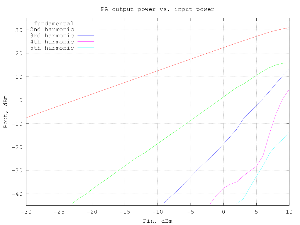
The fundamental and harmonics output levels versus input power, with a 10 MHz sinewave input, are shown in the graph below:
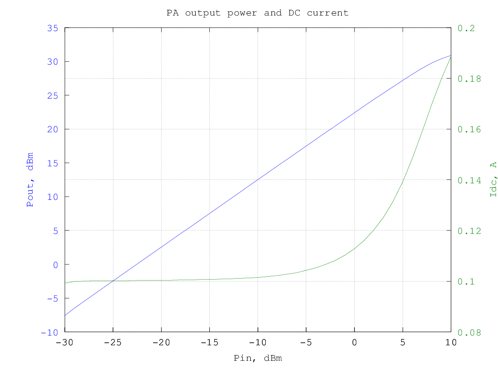
RF output and DC current drawn from the supply versus input power (10 MHz sinewave) are shown in the following graph:
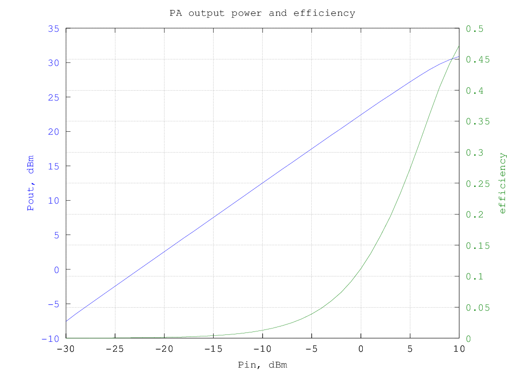
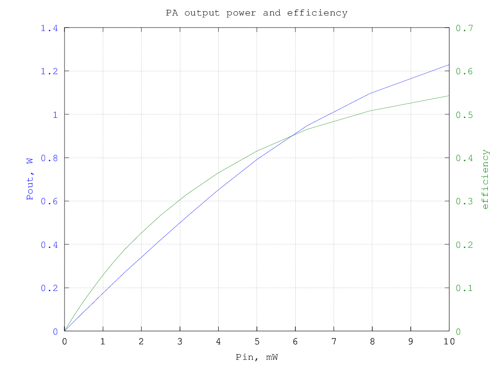
and the resulting efficiency is shown in the graphs below (data are the same for the two graphs, in the first the input and output power are in dBm and in the second they are in watt):
The third-order intermodulation products amplitude w.r.t the output power is shown in the graph below (note that the output power is per-tone, so to have the actual [average] power multiply the value by two, to have the PEP, multiply by 4):

By plotting the third-order intermodulation products power vs. the input power we can find the intercept point by extrapolating the results. The amplifier third-order intermodulation products follow the theoretical 3:1 slope w.r.t. the input power up to about 0dBm input, as can be seen from the graph below:

The input IP3 turns out to be 20.4 dBm and the corresponding output IP3 is 42.7 dBm; these numbers are good but not exceptional.
The graph below shows the relative amplitude of the IMD products (separately for upper and lower products) for a two-tone test with varying tone spacing (the output power is 1 W PEP)
 note that there is a significant variation in the IMD levels with the tone spacing; the dip at around 200 kHz is likely due to the drain supply network (output choke resonating with the local bypass capacitor).
Noise figure
I did also a quick measurement of the amplifier noise figure, just to see if it could be used also as a low-distortion receiver preamplifier. It seems that these devices are quite noisy below 100 MHz and even above they are not particularly quiet. Anyway, the data are a bit noisy, maybe due to the presence of other RF equipments nearby, but I did not have the opportunity to double check the measurements...
