IN3OTD's web site
...under perpetual construction.

Measurements of some transformers for low-bands antennas
Following the recommendations in the well-known ON4UN's Low-Band DXing (4th ed.) - LBDX - (note that there is a newer edition available) some time ago I've built some transformers that can be useful for building low-bands antenna systems.
1:1 transformers
These transformers are built as described in LBDX chapter 7, section 1.22; as explained in the book, they can be used as part of a hybrid combiner or as phase inverters for an RX antenna array. They are built on a binocular BN-73-202 (Fair-Rite 2873000202) with 4 bifilar turns; the wire diameter and the number of twists per inch are not critical for this low-frequency application, so I used a thin wire with a rather thick insulation instead of magnet wire to have a more rugged transformer.
Since they are intended to be part of an antenna array, I built a few of them:
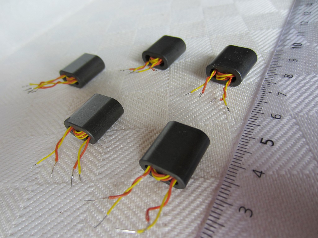
Here below is the measured response for all the 5 transformers above when used as inverting transformers with 50 Ω source and load impedances:
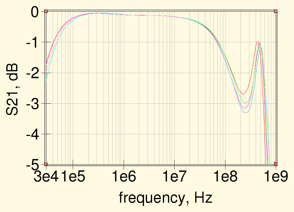
the dip around 150 MHz is due to the non-optimal twisted-wire transmission line impedance, which is certainly quite higher than the optimal 50 Ω; as said, this does not make much difference at the low frequencies of interest here.
The following graph shows the same data zoomed-in around the HF band:
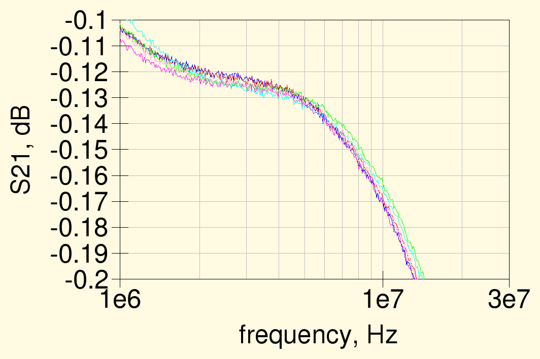
note that the response for all the 5 transformers tested is practically identical and the losses at 1.8 MHz are around 0.12 dB; this is somewhat higher than the "less than 0.1 dB" reported in Fig. 7-25 of LBDX, maybe because of the thin wire used.
Response vs. number of turns
Out of curiosity, I have measured also the response for a transformer wound on the same type of core with different number of turns. In this case the wire used was enameled wire of 0.25 mm diameter, bifilar and twisted at 3 twists per centimeter.
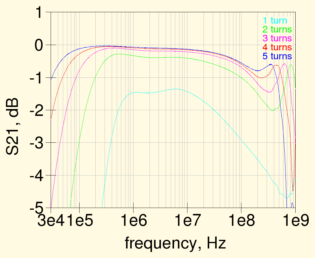
as expected, more turns improve the low-frequency response and worsen the high-frequency end response. Note also that the high-frequency dip moves lower in frequency with more turns, since its position depends on the wire length and it's not as deep as for the previous transformers, since the thicker wire gives a lower characteristic impedance, closer to 50 Ω.
Here below is response for the HF band only:
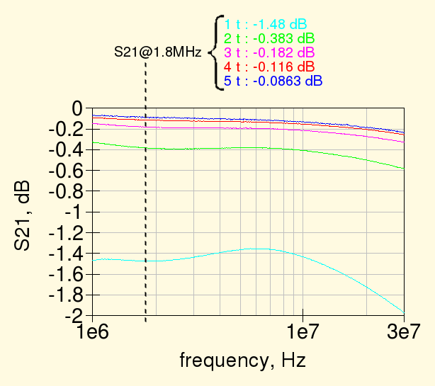
in the end, how many turns to use depends on how much losses or mismatch you are willing to tolerate; for the HF band, using at least 3 turns gives practically negligible losses.
Wideband inverting transformer
While not needed for low-frequency work, the inverting transformers bandwidth can be improved by using a real 50 Ω transmission line wound on the ferrite core; as saw before, using a line with a higher impedance causes a dip in the response around the frequency where the line length is ¼ wavelength long.
The transmission line can be the usual twisted wire, with the proper wire diameter and number of twist per centimeter, or more simply a small coaxial line; as I had some length of micro coaxial cable available, I just used this latter to wound the usual 4 turns:

The following graph show the response of three transformers using the same BN-73-202 core but wound with different transmission lines: the first one uses the above-mentioned 50 Ω micro coaxial cable, the second is wound with a 0.25 mm enameled wire with 3 twists per centimeter and the third uses the thin wire with a thick insulation discussed at the beginning - these last two have a transmission line impedance higher than 50 Ω.
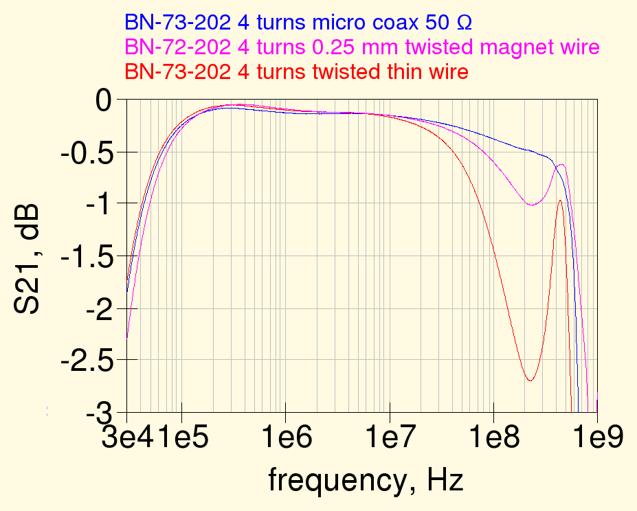
while the low-frequency response is practically identical, the high frequency behaviour is different and, as expected, the 50 Ω line has a flatter response; its high-frequency roll-off starts a bit earlier than the other lines probably due to the higher inter-turns capacitance. Note that this transformer has anyway a bandwidth of more than 4 decades and while its high-frequency response could probably be optimized further that's not necessary for our HF antennas...
Braid breaker
Another kind of transformer useful for low-frequency antennas, is the so called braid breaker, described in LBDX chapter 7, section 2.7.2.10 ; this is a standard transformer, with separate windings, where the inter-winding capacitance should be kept to a minimum.
A couple of transformers were built according the the description in LBDX, with two stacked BN-73-202 cores and two windings with 2 turns each, not twisted, to reduce the inter-winding capacitance.
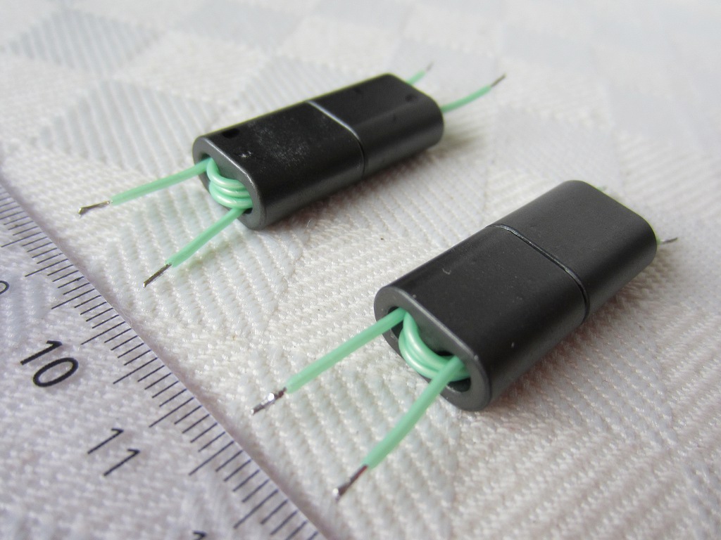
To simplify the construction I did not use the Teflon insulating tubes suggested in LBDX to keep the windings separate but used a wire with thick Teflon insulation. The measured frequency response for the two transformers is shown below:
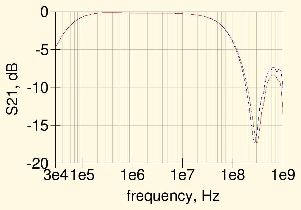
the losses in the HF band are very low and the high-frequency behavior is also quite good; as seen before, there is a dip around 300 MHz due to the high impedance of the pseudo transmission line formed by the windings which purposely have a low inter-winding capacitance and thus a high characteristic impedance.
The zoomed-in HF response can be seen from the graph below:
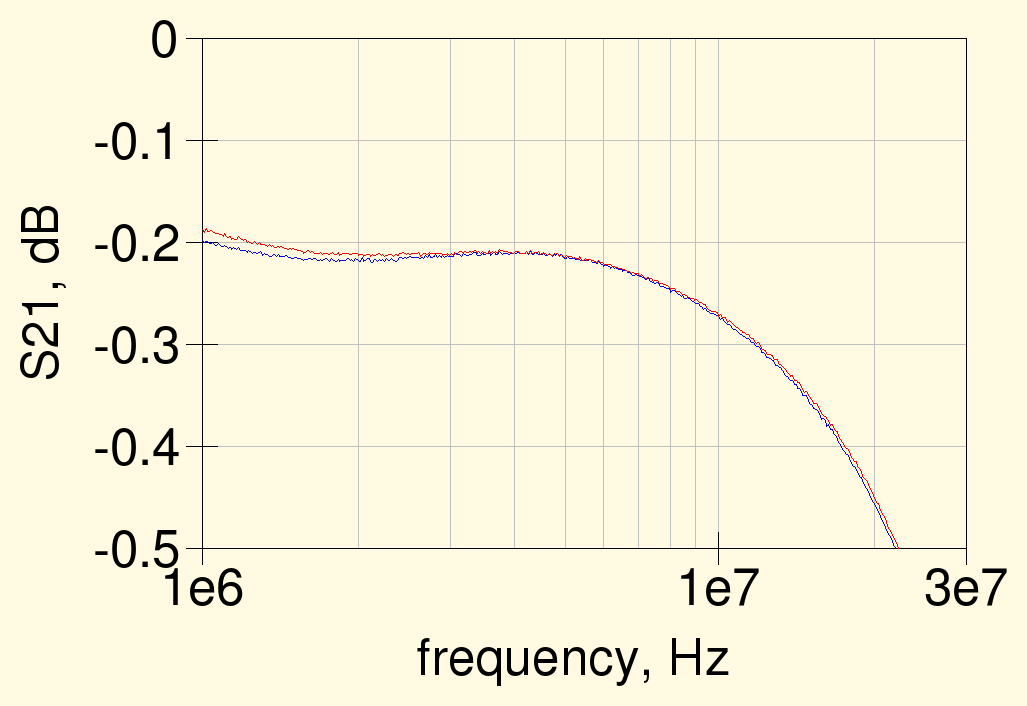
at 1.8 MHz the losses are around 0.21 dB for both transformers, which is slightly higher than the 0.17 dB quoted by LBDX in the chapter 7, section 2.7.2.10 .
Inter-winding capacitance
To measure the inter-winding capacitance, the transformer was connected as shown below, with the windings short-circuited. The measured two-port S-parameters were then used to extract the three parasitic capacitances, Ca, Cb and Cc.
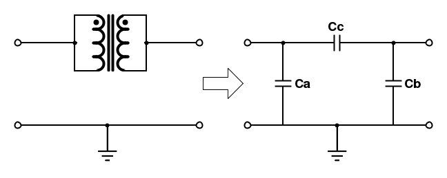
The resulting equivalent capacitances are shown in the next graph (both transformers shown above were measured, respective results are denoted by the suffixes 1 and 2 in the graph below); note that they are fairly constant between 1 and 100 MHz, which confirms that the short-circuited transformer is well approximated by this equivalent circuit in the frequency range of interest.
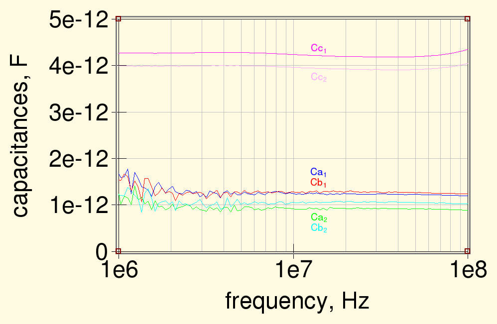
Surprisingly enough, the measured inter-winding capacitance, Cc (around 4 pF), is significantly lower than the value quoted in LBDX of 8 pF for a transformer of this type.