
Navigation
Menu
Center-fed Bent-Dipoles
Horizontal Lateral
Vertical
- OCF
Slow-Wave
Other Topics
Home
On this web site, all studies about bent dipoles are based on identical standard conditions:
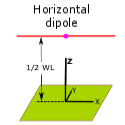
- Antenna feedpoint at 1/2 wavelength elevation over average Summerfield ground.
- Radiating arms/monopoles are made of #14 American Wire Gauge (AWG) copper wire.
- Each model is optimized at resonant frequency for Standing
Wave Ratio at 50 Ohms (SWR) and minimum reactance (j Ohms).
- All models are verified by the Average Gain Test (AGT) range of 0.95-1.05.
- Auto-segmentation is used where antenna arms are different lengths by Off Center Feed (OCF).
- Gain figures are decibels-isotropic (dBi) relative to a
lossless antenna in free space.
Home page: http://www.qsl.net/4nec2/
 The
Standard Horizontal Dipole Characteristics
The
Standard Horizontal Dipole CharacteristicsImpedance: 68.9 -j0.26 ohms (versus 72.0 -j0.23 ohms in free space)
SWR 50: 1.38 (versus 1.44 SWR in free space)
Radiation Efficiency: 74.5%
Gain: 7.32 dBi at 30 degrees elevation above horizontal (versus 2.15 dBi omni-directional in free space)
Beam Width: 30 degrees (half-power points, -3 dBi)
Nulls off ends: -2.7 dbi (This is a total difference of 10 dBi between signals from the sides and the ends).
4NEC2 Antenna Model: Here
Looking at the Figure 1 below:
The Red trace (Hor Plane) is as if you were looking down at the radiation where the top and bottom lobes are 7.32 dBi.
The Blue trace (Ver Plane) is as if you were looking at the radiation pattern from the side where the left and right lobes are 7.32 dBi.
Note the red and green lines from the origin. The red lines indicate at the red dot where the angle of radiation is maximum, 7.32 dBi. The green lines define the 30 degree beam width up from 15 degrees to 45 degrees or down from vertical from 45 degrees to 75 degrees.
The short red bar represents the dipole structure to help understand the shape of the Red trace (Hor plane) radiating from the sides of the dipole
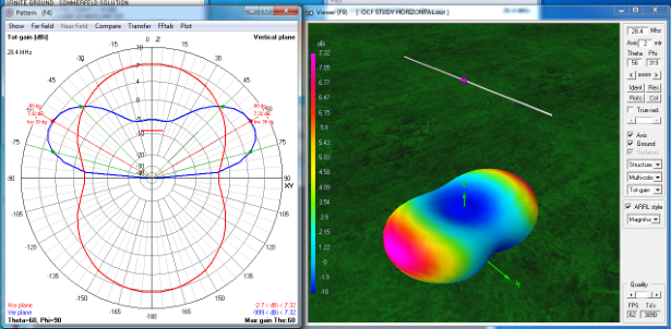
Figure 1
Dipole Polar Graph and 3D view
Dipole Polar Graph and 3D view
The 3D view from above is to make clear the far field radiation pattern represented by the graph.
From the Amateur Radio bible "Gain both giveth and gain taketh away". Note the position of the 3D dipole above, relative to the shape of the dipole radiation below. Note the color scale along the left side that indicates signal strength giveth +7.32 dBi in purple, but taketh away around -3 dBi in dark blue. That represents 10 dBi difference in signal rejection between the dipole sides and the ends.
In free space a dipole has a doughnut shaped ring of radiation around it. As the dipole nears earth, the pattern is squished by reflections from earth. Impedance and resonant frequency as well as radiation angle and gain depend on the height of the dipole over ground and the nature of the soil.
Click here to see a table of the elevation effects on antenna radiation pattern for these bands:
160m,
75/80m, 40m, 20m, 15m, 10m and 6m
Below, are graphs and an animation of what happens to a resonant horizontal dipole according to feed point height over average ground.
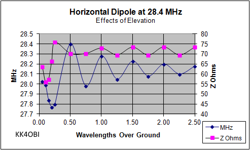
Figure
2
In Figure 2, the big changes near ground stand out. Watch the radical 3D shape from 0.1 to 0.5 WL (Wave Length). Under 1/4 WL, dipole radiation is a circle aimed to the sky. By 1/2 WL the classic broadside radiation pattern is formed. Past 1/2 WL skyward radiation again rises from the center.
On the graph, the impedance (pink squares) drops to give a better match to 50 ohm coax, but the frequency (blue diamonds) of only 28.0 MHz is low. Retuning is required. Moving the dipole only slightly higher, about 1/4 wavelength, the frequency change is greatest (about 27.8 MHz) and impedance is highest (about 75 Ohms). Not as good. If you can have the dipole mounted a little higher, you can see that the situation improves as you approach 1/2 wavelength. Tuning is a bit easier and the SWR will go down slightly.
At 0.5 wavelength the 3D radiation pattern is the best... clean and low angle. Its 70 Z Ohms will be close to 50 Ohm coax (70/50=1.43 SWR). Also, it is on the highest frequency and shortest length that a dipole obtains at any elevation. (This frequency maximum effect is a diagnostic. At this point the difference between the actual height and the calculated 0.5 wavelength height reveals where your particular radio frequency ground exists. In dry, sandy soil the RF ground will be deep and indistinct compared with the sharp maximum of a field day ocean beach setup).
Greater height means a trend to lower frequency and longer length. Notice on the graph that the MHz oscillates up and down converging on 28.15 MHz (about 0.9% low) as the dipole approaches free space.
Also, every additional 0.5 WL in height adds another sky-warming ground reflection to the radiation pattern. This increasingly complex effect can be seen in the animation at 1.0, 1.5 and 2.0 WL.
Similarly, the Z Ohms impedance oscillates between 70 and 74 presumably converging on its free space value of 72 Ohms.
Finally, note that the oscillations are out-of-phase lower than 0.5 wavelength and in-phase above 0.5 wavelength.
You may want to experiment with height to improve antenna SWR and desired radiation pattern.
Dick Reid, KK4OBI at QSL.net