
Navigation
Menu
Center-fed Bent-Dipoles
Horizontal
Lateral
Vertical
- OCF
EFHW
Slow-Wave
Other Topics
 What
Happens If You...
What
Happens If You...Bend the Ends of a Vertical Dipole?
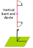
In this study the antenna modeling procedure starts with the optimized resonant length of our "Standard Vertical Dipole" and progressively shortens it, 0.9, 0.8, etc. At each ratio the optimizer function finds a new total length that will resonate on frequency when the antenna is in the bent form.
For example, at a ratio of 0.6 the overall wire length is 3.3% longer. The vertical portion is 60% long and each right-angle bend is at 20% from the top and 20% from the bottom. The vertical is center-fed at 1/2 wavelength over ground.
4NEC2 Antenna Model: Here
Below, the studies look at what happens when the bends are
on the same side or opposite sides.
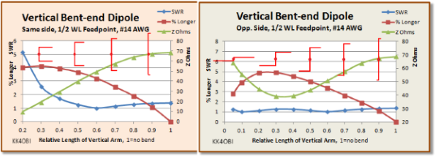
Figure 1
A graphic indication of the bent ends is shown in red.
The general
expectation for a bent vertical dipole as it gets shorter is:
- The Frequency goes higher. The antenna must be
longer to maintain resonance. (Red line)
- The Z Ohms impedance goes down. It passes through 50
ohms at some point. (Green line)
For bend ratios down to 0.6 to 0.5
there are no particular
concerns. In that range adjusting the wire 3% - 4% longer, the SWR
50 can be under 1.4. Notably, at the 0.6 point
there is a near perfect match for coaxial cable.
However, when the vertical arm gets shorter than the 0.5 point the character of the antenna changes. The greater part of a dipole's radiation is in the center, in this case vertically polarized. But as the total length of the two horizontal bends become greater than the length of the vertical arm, the antenna increasingly becomes horizontally polarized and overwhelms the vertical characteristics.
When the bends are on the same side there is no gain to the sides at ratios less than 0.5. The two long horizontal sections start to act more like a phased array aimed upward. This potentially could be useful for Near Vertical Incidence Skywave communications, NVIS.
When the bends are on opposite sides, the two long bent sections start to act more like a horizontal dipole. Between 0.3-0.4 bend ratio the SWR peaks at around 1.3 and starts downward to give a near perfect match at a 0.15 bend ratio. This interesting configuration is basically a jog at the center of a horizontal dipole which reduces the length by 15%. Lateral Gain is 6.9 dBi at 30° takeoff angle with a 6 dBi null off the ends. Radiation Efficiency is over 71%.
The unusual characteristics of
a vertical bend end dipole are what happens to
Gain and Radiation Efficiency.
Gain and Radiation Efficiency.
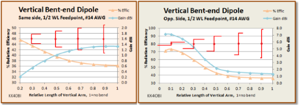
Figure 2
A graphic indication of the bent ends is shown in red.
In the "Same Side"graph
in Figure 2, it would appear that Gain (blue line) is a problem
as the bend ratio is less than 0.5. The reality is that
the vertical radiation becomes dominant as the radiation from
the bent ends becomes dominant. At 0.3 ratio, gain is 1.5 dBi. At
0.2 ratio gain = 2.4, dBi but aimed skyward. Radiation Efficiency
(orange line)
also appears to rise but don't be fooled, that is also aimed skyward
thus favoring a NVIS application.
On the "Opp. Side" graph in Figure 2, the Gain (blue line) of a vertical bent-end dipole defies logic by going up as the bend ratio gets smaller... exactly the opposite of normal. Of course the rise in gain is from the horizontal parts gradually becoming more like a horizontal dipole which has gain over 7 dBi.
Radiation Efficiency (orange line) also goes the wrong way but for a different reason than the "Same Side" bent dipole which efficiently sends radiation skyward. In this case the mixed vertical-horizontal polarity radiation is becoming stronger to the sides, more like a horizontal dipole.
All this is informative, but the Far Field Radiation patterns with flyover 3D view really dramatize what happens when you bend the ends of a vertical dipole.
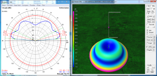
Figure 3 Same
side bend at 0.6 ratio
The above graph looks much like the Standard Vertical Dipole: Circular with the radiation angle at 15° up from horizontal and a beam width of 20°. Gain is reduced as expected, 1.16 dBi vs. 1.33 dBi but SWR 50 is a near perfect 1.01 with Impedance at 49.6 ohms, j = +0.38. The difference to note is the larger ground wave (green) at 35°- 40° from vertical. This is due to the horizontal polarization from the bent ends.
Now see what happens when the vertical section is shorter (0.3 ratio) than the total length of the bends.
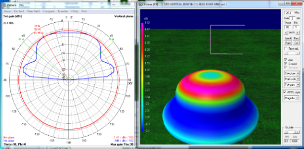
Figure 4, Same side bends
at 0.3 ratio
Still circular radiation like vertical dipole but shaped like a Derby Hat. The low angle radiation is now negative and most of the radiation is 1.5 dBi upward at 30° from vertical with a half-power beam width of 100°! The Radiation Efficiency is good, over 43% but the Impedance is only 19 ohms so the SWR at 2.6 may require a tuner for NVIS work. At 0.2 ratio the Derby Hat radiation pattern is even more pronounced, the skyward Gain rises to 2.4 dBi and the impedance drops to less than 10 ohms. Not good.
Now we look a what happens to a dipole where the ends are bent to opposite sides.
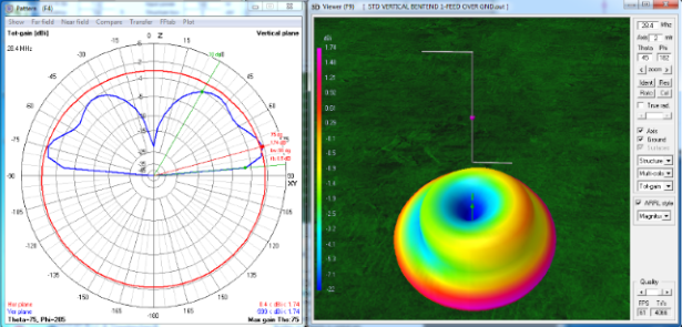
Figure 5, Bends on
opposite sides, 0.6 bend ratio.
On Figure 5, the first thing to note is that the radiation is not quite circular (red line). Also, the lobes on the graph (blue line) are a little larger to the right. Look at the 3D view. There is more signal (purple) coming from the bend closer to the ground. The gain in that direction is 1.74 dBi as compared with 1.16 dBi when the bends are on the same side. The SWR 50 is a near perfect 1.02 with Impedance at 50.8 ohms, j = +0.13. The low angle radiation remains at 15° up from horizontal however the half-power points now include the ground wave bulge at 45°.
Now let us compare the far field radiation pattern at 0.3 ratio.
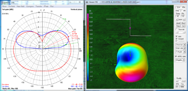
Figure 6, Bends on
opposite sides, 0.3 bend ratio.
The striking things seen on Figure 6 are the kidney bean shape (red line) and the absence of skyward radiation (blue line). Looking at the 3D picture, there is a -19 dBi null off the upper side bend, zero gain off the lower side bend and 5.26 dBi gain broadside to both horizontal bends. The antenna is becoming a horizontal dipole. The SWR 50 is 1.28 with Impedance at 39.1 ohms, j = +1.32. The radiation angle is higher at 25° up from horizontal with a beam width of 40°. The antenna is 4.1% longer and mixed vertical/horizontal Radiation Efficiency is 60% compared with 36% for the Standard Vertical Dipole.
Because the antenna above has almost become a dipole, let us see what happens at 0.1 ratio.
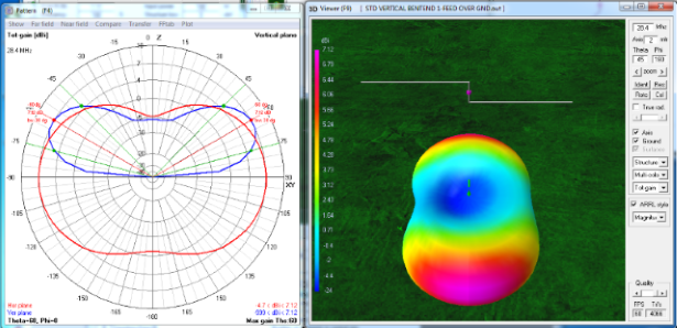
Figure 7, Bends on
opposite sides, 0.1 bend ratio.
On the Figure 7 we see an almost symetrical far field radiation pattern (red line) and a higher radiation angle (blue line) at 30° up from horizontal with a narrower beam width of 30°. Looking at the 3D picture, there is a -4.7 dBi null off the upper side bend, and weaker -2 dBi null off the lower side bend. Gain is 7.12 dBi broadside to the horizontal bends. The antenna radiation pattern is very close to looking and performing like a horizontal dipole. The SWR 50 is 1.11 with Impedance at 55.6 ohms, j = +0.4. The antenna wire is 5.3% longer and Radiation Efficiency is the same as a Standard horizontal Dipole even though this bent dipole antenna length is 10% shorter.
Comments
Tuning. In the study about lateral bent-end dipoles there is a section about tuning by adjusting the angle of bend +/- 90° if the antenna resonates within +/- 10% of target frequency. This technique also applies for vertical bends but with a slight compensation for the bend near ground.
Shorten. By experimentally increasing the 90° angle between the arms into a Z-angle of around 120-125°, this Z-overlap can give:
1. matching for a 50 ohm coaxial cable,
2. narrowing of the offset space between horizontal arms and
3. shortening of the overall dipole length by around 13-14% .
Dick Reid, KK4OBI at QSL.net