
Navigation
Menu
Center-fed Bent-Dipoles
Horizontal
Lateral
Vertical
- OCF
EFHW
Slow-Wave
Other Topics
 What happens
if...
What happens
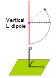
if...a Vertical Dipole is Bent into a "L"?
This page is the companion to the Horizontal L-dipole discussion. Here, the computer model starts with a standard vertical dipole fed in the center at 1/2 wavelength over average ground. For the study, the upper arm is held fixed. Nothing about it changes.
However, the lower arm is variable and swings at the center feedpoint. For this study the lower arm is adjusted in steps of 15°. As this arm swings upward from vertical, the dipole's electrical length becomes shorter and the resonant frequency rises. The optimizer function of the antenna model iteratively searches for the longer length that gives the lowest SWR50 and +/- j reactance.
By adjusting only the length of the variable arm it becomes progressively longer than the fixed upper arm. The slight asymmetry introduced is small versus the great convenience of using a single telescoping end-section for tuning. In contrast, the studies on bent-end and V-dipoles are symmetrical... optimized for full length before bending into the resonant form. The effects of symmetry are discussed in the OCF (Off-Center-Feed) pages.
4NEC2 Antenna Model: Here
Let us look in Figure 1 at the results of the computer model. Note the graphic representations, in red, of a dipole bent to various angles.
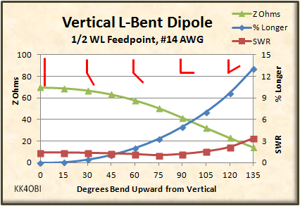
Figure 1
A graphic indication of the L-bend is shown in red.
As always, the best performance of a half-wave dipole, vertical of horizontal, is a from a straight radiator. Any bend causes the impedance (green line) to become lower and the resonant frequency to rise. To maintain the desired frequency the variable arm must be some % Longer (blue line).
In general, the impedance of a straight dipole, vertical of horizontal, is around 70 ohms which is a SWR (red line) of around 1.4 to 1. As a dipole is bent the impedance falls passing through 50 ohms on the way down. In this case the magic angle is 75° up or 15° below horizontal where the arm is 3.33% longer. At this point the model gives SWR 1.01 to 1 at +0.05 j reactance with gain of 3.66 dBi towards the direction of the variable arm. Gain? How can there be gain with a vertical dipole whose maximum gain is 1.57 dBi?
If you bend a horizontal dipole, dBi gain goes down. The reverse is true in a vertical dipole, dBi gain (as well as % Radiation Efficiency) goes up steadily as the bend increases. For example in figure 1, at the maximum bend angle of 135° the gain is 5.63 dBi but at a cost of a SWR of 3.38 to 1. Interesting but not attractive.
Rather than publish graphs of Gain, Front-to-Back ratios and % Radiation Efficiency, let us look instead at the subtle changes in far field radiation patterns a various angles of bend. As you will see there is a complex set of ways a bent vertical dipole can be used.
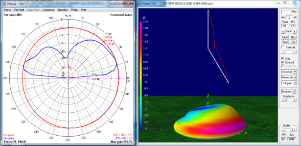
Figure 2, 30 degree bend
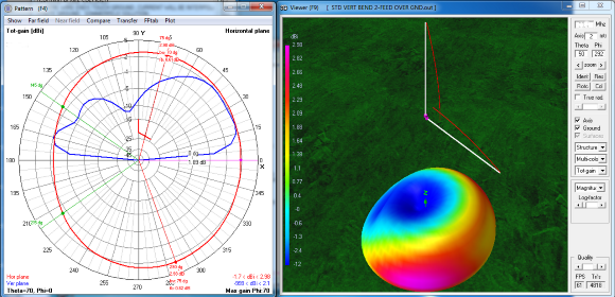
Figure 3, 60 degree bend
In Figure 3 notice that the low-angle/high-angle bulge is getting
bigger and the red ring on the graph is flattened on the back side
(180°) down to -1.7 dBi. The gain given is 2.98 dbi but here is
where charts do make it clear. Actually that this gain occurs at 75° up
and 290° down (red ring), not at where the arm points (90°). The
gain is only 1.89 dBi, about the same as the vertical dipole.Look at the 3D picture and see that the maximum gain (purple) is now aimed low and at either side of the side arm. This means that as you rotate the antenna the signal will drop 2.98 + 1.7 = 4.68 dBi from the 75°and 290° strong points to the back side at 180°. Front-to-back (0°-180°) the difference in signal is still good, 1.89 + 1.7 = 3.59 dBi... about twice as loud.
Finally, higher angle radiation (45°) is becoming significant. Note on the 3D picture that there is a red band under the side arm where the signal strength is a flat 2 dBi for more than a semi-circle. This could be handy for non-DX work.
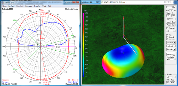
Figure 4, 90 degree bend. The
L-antenna
In Figure 4 the red kidney bean shape catches the eye. The bulge is hot
on the ends. There is now more signal up at 85° and down at 280°, 4.34
dBi. Even less on the back at 180°, -4.2 dBi.. The antenna
behaves more like a horizontal dipole where the strongest signal is to
the sides. This is the same pattern as a horizontal dipole when
bent into the L form. Directionality is significant. When you rotate this antenna, the difference between the strong points and the back is 4.34 + 4.2 = 8.54 dBi. Even though the gain at 0° towards the bend arm is now down to 1.01 dBi, the front-to-back (0°-180°) ratio of 4.2 + 1.01 = 5.21 dBi is still a very distinct difference to the ear or S-meter.
Finally, higher angle radiation (45°) pales in the onslaught of the stronger side-to-side radiation. Note on the 3D picture that there is now only light green band under the side arm where the signal strength is a flat 1 dBi for more than a semi-circle. This says that the L-antenna works almost like a vertical towards the side arm, but really shines (red/purple) to the sides of the arm.
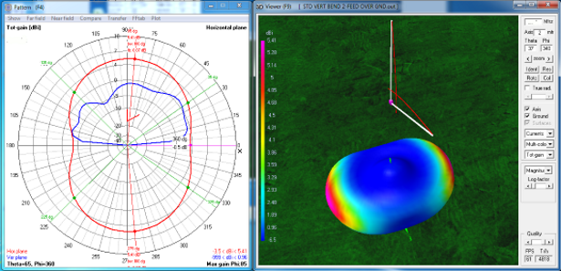
Figure 5, 120° bend
In figure 5 the kidney bean shape is almost gone. The radiation pattern
is almost like that of a dipole. There is no vertical antenna
characteristic evident. Gain of 5.41 dBi (red/purple) now refers only
to the sides of the side arm. The beam width at half power (-3dB)
is 100° wide on both sides See 135° to 35° (green lines up) and
225° to 325° (green lines down). On the back (180°), signal
rejection is -3.5 dBi so rotation of the dipole gives an impressive
5.41 + 3.5 = 9.11 dBi between the strong points to the sides of the "L"
and the area opposite the side arm. Signal rejection in the
direction of the side arm (0°) is -0.5 dBi so there is still a
significant 6 dBi difference between the strong points.From the above figures it can be seen that an "L" bent vertical dipole can be as need dictates:
- A space saving design... only an 1/4 wave at the widest
- A vertical with more than double-gain
- A half-dipole with more than half-gain