
Navigation
Menu
Center-fed Bent-Dipoles
Horizontal Lateral
Vertical
- OCF
Slow-Wave
Other Topics
Home
 In
addition to the generally known "slow wave" techniques of zig-zag and
meander, the studies presented here cover the technique
of multiple curves to shorten the arms of a dipole. This approach
is a logical extension of the work on
Dipole Sag and the associated development of an antenna model
for Catenary Curves.
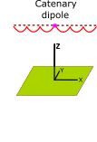
It was found that if a Catenary dipole was set to sag 35% of the length
of a resonant wire, there would be a match for 50 Ohm coaxial
cable. Ease of use set aside, this is a rather large drooping
antenna with a broad, higher angle beam. Why not keep the center
feed at the same height as the ends and allow the arms of the dipole to
droop but only half as much? A 2-Droop 4NEC2 Model: Here,
was
developed which answers the question:
In
addition to the generally known "slow wave" techniques of zig-zag and
meander, the studies presented here cover the technique
of multiple curves to shorten the arms of a dipole. This approach
is a logical extension of the work on
Dipole Sag and the associated development of an antenna model
for Catenary Curves.
It was found that if a Catenary dipole was set to sag 35% of the length
of a resonant wire, there would be a match for 50 Ohm coaxial
cable. Ease of use set aside, this is a rather large drooping
antenna with a broad, higher angle beam. Why not keep the center
feed at the same height as the ends and allow the arms of the dipole to
droop but only half as much? A 2-Droop 4NEC2 Model: Here,
was
developed which answers the question:What happens if both sides of a dipole are
drooped?
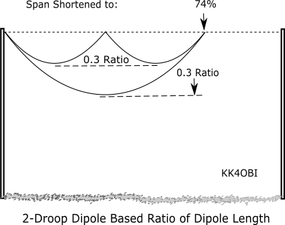
Figure 1
From Figure 1. The 2-Droop characteristics compared to a 1-Droop catenary dipole are:
Z impedance: 52.7 Ohms vs. 60.4 Ohms
SWR50: 1.06 vs. 1.21
Gain: 6.39 dBi vs.5.81 dBi
Radiation Efficiency: 71.93% vs. 76.05%
Resonant Wire Length: 5.08% longer vs. 1.04% (Longer than a straight dipole)
Clearly, a 2-Droop dipole is prefered if you accept a longer resonant wire length.
The Far Field Radiation pattern looks very much like that of an ordinary straight dipole.
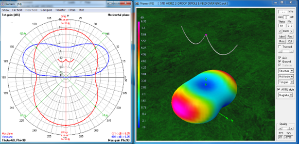
Figure 2
Far Field Radiation Pattern, 2-Droop Dipole at Resonance
Here is a comparison of Figure 2 to a 1-Droop cantenary dipole as in Figure 1:
Angle of maximum radiation (Purple color on 3D view) is 30° up from horizontal vs 40° for the 1-Droop cantenary dipole.
Beam width (at 3dB down) 90° vs 110°.
End Null: -3.1 dBi vs -1.5 dBi (Better than the -2.7 dBi of a straight dipole).
Side-to-End Ratio: 9.5 dBi vs.7.3 dBi (Close to the 10 dBi of a straight dipole).
To extend this idea of multiple droops, a 4-Droop 4NEC2 Antenna Model: Here, was developed which answers the question:
What happens if there are two droops
on each side of a dipole?
on each side of a dipole?

Figure 3
Surprisingly, the answer is "No apparent change". Even though the physical depth of a droop becomes much smaller for the 6-Droop and 8-Droop antenna models, their radiation characteristics turned out to be virtually same. Really unexpected.
Because of this visual commonality of the graphs for each of the 2-,4-,6- and 8-Droop Catenary Dipoles, the graphs were consolidated into the following three figures.
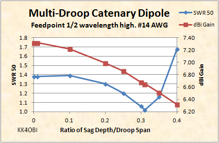
Figure 4
In Figure 4 the Blue line for SWR as before, rises then falls to to a perfect 1:1 match around 0.30-0.32 ratio.
The Red line shows the familiar, unrelenting decrease in dBi Gain for increasing ratios of sag.
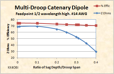
Figure 5
Figure 5 confirms that all Multi-Droop configurations have a 50 Ohm impedance around 0.30-0.32 sag ratio (Blue Line) and sag ratio has little effect on % Radiation Efficiency (Red Line).
The single signigficant difference between the 2-,4-,6- and 8-Droop antennas is the length of wire needed.
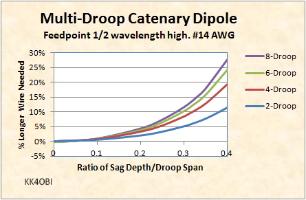
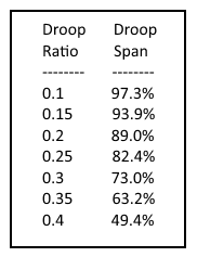
Figure 6
The Cantenary antenna models are based on finding the starting length of wire that, when bent, will resonate the same as a straight wire. As the depth of each droop and the number of droops increase, the % longer lengths of wire needed are summarized in the four curves of Figure 6 above. For example: To build a 6-Droop Catenary dipole for the 50 Ohm resonant frequency, you need to start with wire that is 10% Longer than the amount of wire that is resonant as a straight dipole... then divide it into six segments.
In Figure 7, compare the 8-Droop Dipole Polar Graph and 3D flyover view with Figure 2. You can see that they are virtually identical indicatiing that the number of droops has no apparent bearing on radiation characteristics. 4NEC2 Antenna Model: Here
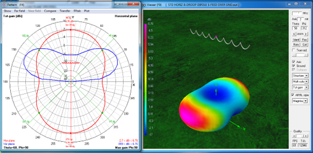
Figure 7
Far Field Radiation Pattern, 8-Droop Dipole at Resonance
Some practical points for building: Your target frequency has a bearing on the number of droops to decide upon. For HF more droops means more work but a more controllable, less wiggly, compact antenna. VHF can get along with 4 or 6 droops. UHF, attic or wind-free location, 2 or 4 droops could be considered.
The length of a multi-catenary dipole controls the resonant frequency, so hold the length dimension and open the wire in the center enough to accomodate the coax connector or balun. Measure and mark the bend points for each droop before bending. Bend both sides of the antenna at the same time for uniformity. It is not at all critical to have sharp well-formed junctions between curves. It is not critical to try to form a catenary curve. An "S-shape is ok. For tuning, adjust the length of the dipole.
This approach to shortening and tuning a dipole by multiple droops is an extemely tolerant method. Any reasonable approximation will work.
Dick Reid, KK4OBI at QSL.net