
Navigation
Menu
Center-fed Bent-Dipoles
Horizontal Lateral
Vertical
- OCF
Slow-Wave
Other Topics
Home
Compared to the V-antenna or inverted-V, the effects on antenna characteristics of a laterally bent dipole are simpler because the distance to the ground is constant.
 What Happens If...
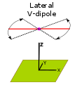
 A Dipole is Bent Sideways
into a "V"?
In the following study, the standard antenna computer model is configured to define any angle as small as 30° between the arms of a dipole bent sideways. The model then optimizes the length of wire that gives the lowest SWR and reactance (R-in) when bent to that angle. Angle data is taken in 30° steps.
4NEC2 Antenna Model: Here
Figure 1 below sumarizes Gain, SWR and Length data the results from computer modeling.
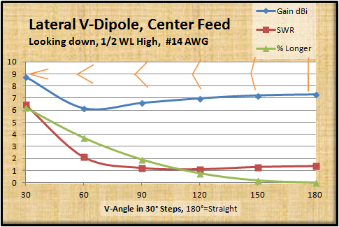
Figure 1
A graphic indication of the V-bend is shown in red.
Note that along the top of the graph, there is representation in red of the V-angle of the dipole as looking down from above.
The first observation is that as a dipole is bent into a V-form, the Gain dBi goes down (blue line). Curiously, as the V-angle becomes less than 60°, the gain rises... unfortunately so does the SWR.
This also happens when the V-arms are oriented vertically.
As the V-angle gets smaller, the impedance goes down from the normal 68.9 ohms and passes through 50 ohms to give a match with coaxial cable. Looking at the SWR curve (red line) this 50 ohm point occurs with the V-angle around 120°.
The length of wire (green line) needed to maintain resonance increases as the amount of bend increases. A practical bend maximum would be at around 80°-90° V-angle and 2% longer. Antenna performance falls significantly at angles narrower than this.
Does the V shape increase signal?
No.
The far field radiation is always basically the same as a dipole no matter the angle of the V.
Contrary to popular myth about V-beams, antenna modeling shows that no discernable front-to-back ratio develops at any degree of lateral V-bend in half-wave or full-wave dipoles. Increased signal only applies for 3-halfwave Gull-wing antennas, multi-wavelength V-beams or full rhombic Diamonds.
Figure 4 below shows the the far field radiation pattern and 3D view of a half-wave lateral V-dipole optimized for coaxial cable feed.
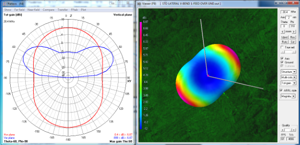
Figure 4
Far field radiation; Polar graph and 3D flyover view
Far field radiation; Polar graph and 3D flyover view
- Lateral V-Angle: 125.1°
- Impedance: 51.3 ohms, j=0.26, SWR: 1.03
- Gain: 6.87
dBi, Side Null: -0.4 dBi
- Maximum Radiation Angle: 60°, -3dB Beamwidth: 30°
- Length increase: 1.07%
Dick Reid, KK4OBI at QSL.net