
Navigation
Menu
Center-fed Bent-Dipoles
Horizontal Lateral
Vertical
- OCF
Slow-Wave
Other Topics
Home
Any length of wire has a resonant frequency. Think of a guitar string. If you touch it in the middle you now have two halves at twice the frequency. Touch at one-third you get three sections at three times the resonant frequency. At one-fourth, get four sections at four times the resonant frequency, et cetera. These are harmonics.
Starting with a wire that resonates at 80 meters (3.5 mHz), the second harmonic is two halves at 40 meters (7 mHz); third harmonic is three parts at 30 meters (10.5 mHz); 4th is four parts 80/4=20 meters (14 mHz). 5th = 17 meters (17.5 mHz). 6th = 15 m (21 mHz). 7th =12m (24.5 mHz). 8th = 10m (28 mHz).
Antenna modeling shows that a resonant half wave wire can be fed at any point (End, Off-Center, Center) without changing gain or efficiency... only impedance. Away from center, impedance is high so a transformer is used to match an antenna to coaxial cable. At 8% from the end is the unique feedpoint where harmonics number 2 to 8 fall into best alignment. At this point the Standard Deviation between those seven resonant length's is only 0.3 meters. These can be aligned with the 1st harmonic by using a small inductance and capacitance.
What
Happens
If...
You Transmit on Harmonics of a
Inverted-L EFHW Antenna?
You Transmit on Harmonics of a
Inverted-L EFHW Antenna?
 To answer the question, a wire antenna model was
developed*
based on data reported by Danny Horvat, N4EXA and E73m
(MyAntennas.com), a
model by VE3KL and the
spherical geometry technique used for the Bent Dipoles "Elevated
Radials"
study.
To answer the question, a wire antenna model was
developed*
based on data reported by Danny Horvat, N4EXA and E73m
(MyAntennas.com), a
model by VE3KL and the
spherical geometry technique used for the Bent Dipoles "Elevated
Radials"
study.4NEC2 Antenna Model: Here
The pattern of antenna radiation is dependant on Wavelength Height, the distance in wavelengths above the ground. The general rule is to position an antenna is "as high as wide". This half-wave elevation provides the maximum signal to the sides with minimum signal skyward. No feedline is considered.
Click here to see a table of the elevation effects on antenna radiation pattern for these bands: 160m, 75/80m, 40m, 20m, 15m, 10m and 6m
Note: Every half-Wavelength Height adds a figure-8 broadside to any half-wavelength of wire. A round reflection dome develops between each half-wavelength.
As seen from the table, an 80 meter antenna at half-Wavelength Height should be at 129.5 feet. This is impossible for most amateur radio operators, therefore the modeling data that follows is based on a 40 foot feedpoint elevation (12.2 meters). This is a practical maximum for commercial masts, telescoping poles and trees.
If you must mount an antenna lower, remember that the closer the to ground: (1) the more signal absorbed by the ground; (2) the remaining signal is increasingly reflected skyward. (You can use the above 4NEC2 antenna model to see what happens at specific elevations and bands).
Model Data by Harmonic
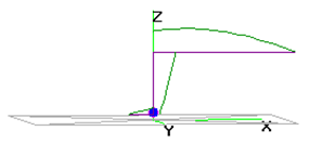
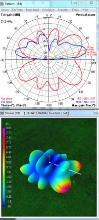
The following data are for the far field radiation patterns and 3D color views of an End Fed Half Wave Inverted-L antenna with a long, straight radiator at 40 feet and feed point straight down near ground.
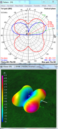
Red color indicates the stronger radiation on 3D views. The direction of radiation is the Blue trace on the polar graphs. Horizontal is 90°. Up is 0°.
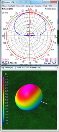
| 80m
Fundamental 1 lobe 3.39 dBi at 5° |
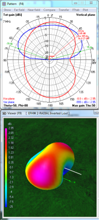
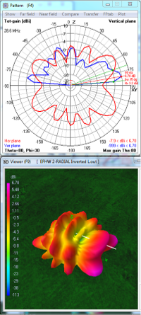
40m
2nd Harmonic 2 lobes 2.95 dBi at 50° |
30m
3rd Harmonic 4 lobes 5.31 dBi at 60° |
 |
 |
 |
On 80 meters, the L-shape reduces the signal strength almost half, to 3.39 dBi as compared with 6.06 dBi when straight. The elevation at 40 feet is a small fraction of an optimal 130 foot half-Wavelength Height so the signal is mostly reflected upward in an oblong shape. Not seen but within the 3D pattern are both vertical and horizontal polarizations. The vertically polarized signal aligns with the wire; horizontally polarized signal is broadside to the wire.
This means that the the figure-8 dipole radiation pattern that we visualize is buried within the RF field and it drops away rapidly. At a 15° take-off angle, the signal strength broadside for DX is down to a -4 to -5 dBi QRP level. Usable but very weak. Radiation from the vertical wire fills the nulls off the ends of the wire to make the round shape. Because maximum signal strength is skyward, the antenna is more suitable for short range NVIS communication.
 On 40 meters,
the
wire now resonates as two half-waves. One of those half-waves is
horizontal to form a dipole-like radiator. Because the horizontal
elevation is now approaching the 65 foot half-Wavelength Height,
directionality develops. The radiation from the horizontal wire is in
the form of figure-8 lobes on each side of the wire.
Radiation from the vertical wire aligns with the wire and fills in
between the horizontal lobes to make the oblong radiation pattern seen
in the 40
meter 3D
picture above.
On 40 meters,
the
wire now resonates as two half-waves. One of those half-waves is
horizontal to form a dipole-like radiator. Because the horizontal
elevation is now approaching the 65 foot half-Wavelength Height,
directionality develops. The radiation from the horizontal wire is in
the form of figure-8 lobes on each side of the wire.
Radiation from the vertical wire aligns with the wire and fills in
between the horizontal lobes to make the oblong radiation pattern seen
in the 40
meter 3D
picture above. The vertical wire also contributes weakly (-5 dBi at 30° take-off angle) in the direction away (left) from the high wire.
Ground reflection is still dominant causing maximum signal at a relatively high angle of 50°. At 15° up from ground the signal strength for DX is 0 to 1 dBi... about half-power. Useful broadside. Nulls are off the ends.
 On 30 meters, the wire
resonates in three half-waves, approximately one vertically and
two horizontally. This causes the horizontally polarized
radiation to divide neatly like a four-leaf clover. The leafs
are aligned
diagonally to the wire with each leaf providing around 4 dBi
directional gain.
On 30 meters, the wire
resonates in three half-waves, approximately one vertically and
two horizontally. This causes the horizontally polarized
radiation to divide neatly like a four-leaf clover. The leafs
are aligned
diagonally to the wire with each leaf providing around 4 dBi
directional gain.The vertically polarized portion of the signal produces two lobes but now are aligned with the wire. The vertical lobe to the right is stronger. Both vertical lobes fit in between, and add to, the four horizontal lobes to produce the two broadside elongated patterns as seen in the 30 meter 3D picture. Signals are stronger at 45° from the wire (red ends) with the right end at 5.31 dBi versus 3.77 dBi from the left end. A -5 dBi null is between the two strong elongated patterns.
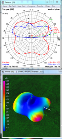
| 20
m 4th Harmonic 4.lobes 6.02 dBi at 70° |
15m
6th Harmonic 8 lobes 8.01 dBi at 75° |
10m
8th Harmonic 10 lobes 6.78 dBi at 80° |
 |
 |
 |
 On 20 meters,
the antenna resonates in four half-waves. Like 30 meters, the
radiation pattern develops four lobes each at 45° from the horizontal
arm. Gain from the lobes is about two-thirds of that of a straight
antenna, 6 dBi compared to 8.92 dBi. Relative to the 30
meter pattern, the peak radiation angle is lower, 70°, which is a
better take-off angle of 20° for DX.
On 20 meters,
the antenna resonates in four half-waves. Like 30 meters, the
radiation pattern develops four lobes each at 45° from the horizontal
arm. Gain from the lobes is about two-thirds of that of a straight
antenna, 6 dBi compared to 8.92 dBi. Relative to the 30
meter pattern, the peak radiation angle is lower, 70°, which is a
better take-off angle of 20° for DX.Radiation from the vertical arm is aligned with the antenna and predominantly fills in the left side as seen above in the 20 meter 3D picture. Gain this direction (left) is 4.5 dBi and at a higher angle, 50°. The slight bump in the middle is ground reflection because the 40 feet elevation is slightly higher than the 35 feet half-Wavelength Height.
Reminder: A vertical dome develops between each half-Wavelength Height.
 On 15 meters,
the antenna resonates in six half-waves, four horizontally. In this
situation those four dipoles have lobes on each end so we see only
eight
lobes in the 3D picture... four lobes on each side of the
antenna. Because the 40 feet antenna elevation is between two 23
foot half-Wavelength Heights, there is a dome. Because the antenna is
close to two half-Wavelength Heights (46 feet), the second set of lobes
for
two half-wavelengths has almost completely formed. The vertical arm
contributes the two larger vertical domes seen on each end.
On 15 meters,
the antenna resonates in six half-waves, four horizontally. In this
situation those four dipoles have lobes on each end so we see only
eight
lobes in the 3D picture... four lobes on each side of the
antenna. Because the 40 feet antenna elevation is between two 23
foot half-Wavelength Heights, there is a dome. Because the antenna is
close to two half-Wavelength Heights (46 feet), the second set of lobes
for
two half-wavelengths has almost completely formed. The vertical arm
contributes the two larger vertical domes seen on each end.Gain is good, 8 dBi off the major lobes which are 35° to the right and left of the wire. The secondary lobes are 15° from broadside with 3 to 4.5 dBi gain. For DX the take-off-angle is 15° for all eight lobes. However, there are also eight nulls between -8 to -12 dBi leaving the antenna hard-of-hearing off the ends, the sides and at 30° from broadside.
 On 10 meters,
the antenna resonates in eight half-waves, five horizontally. This
produces ten lobes, five on each side of the antenna wire. Because the
40 foot elevation is over two half-Wavelength Heights there are two
rings of lobes. Because the elevation is mid-way between two and
three half-Wavelength Heights there is strong dome of ground reflection.
On 10 meters,
the antenna resonates in eight half-waves, five horizontally. This
produces ten lobes, five on each side of the antenna wire. Because the
40 foot elevation is over two half-Wavelength Heights there are two
rings of lobes. Because the elevation is mid-way between two and
three half-Wavelength Heights there is strong dome of ground reflection.The vertical arm produces the pronounced 30° angle vertically polarized lobe at the far right of the 10 meter 3D picture. For DX, gain is 6.78 dBi from this and the two main lobes having a 10° take-off-angle. The remaining eight lobes provide from 1 to 4 dBi gain. However, there are also ten nulls between -9 to -14 dBi leaving the antenna with a complex, porcupine-like pattern with directional difficulties in communication.
The patterns for 17 meters and 12 meters are not included to simplify visualiation.
All 3D views are from the same angle and compass heading.
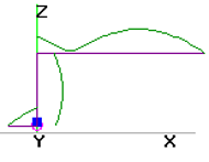
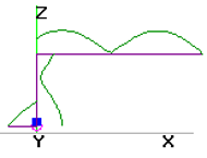
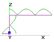
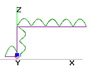
* Note: In the antenna current diagram (top) there is a simulated counterpoise and small inductance (blue square) at the feedpoint (purple circle). Presumably this causes the model's predicted signal to be slightly stronger at the opposite end.