Navigation
Menu
Center-fed Bent-Dipoles
Horizontal Lateral
Vertical
- OCF
Slow-Wave
Other Topics
Home
As an outgrowth of the 4NEC2 antenna models developed for this web site, a study was done related to the frequencies generated related to the harmonic ratios of off-center feedpoints.
What
happens when you feed a dipole off-center?
Starting conditions: 1/2-wave center-fed horizontal dipole of #14 AWG fed at 1/2-wave over ground. The auto-segmentation function is used because of differing lengths of wire.
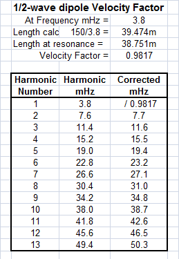 The first run of the study is to find the
center-fed
resonant length of wire for
the target frequency of 3.8 MHz. This is: 38.751 meters.
The
calculated length is 150/3.8 = 39.474 meters. The length ratio of
38.751/39.474 = 0.9817 is refered to as the Velocity Factor. This
is
primarily due to the metal, radius and covering of the wire radiator
and secondarily to its interaction with ground. This factor is
needed
to correct the theoretical MHz to match the MHz of the harmonics
determined in the computer runs ( see
the adjacent table ).
 The series of off-center runs of the 4NEC2 computer model are based on feed points at 1/3, 1/4, 1/5, 1/6 of the resonant length. It is interesting to note that, contrary to conventional dogma, the Resonant Length for 3.8 MHz became longer as the off-center runs progressed. 1 inch at 1/3, 3.39 inches at 1/4, 5.06 inches at 1/5, and 7.28 inches at 1/6 for a 127 foot dipole.
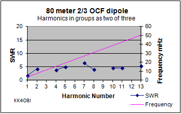
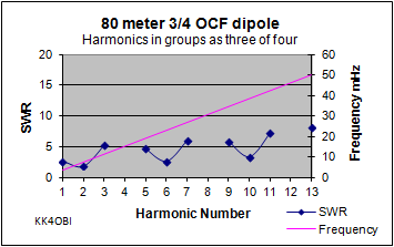
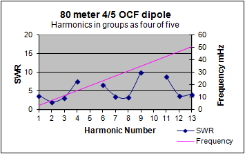
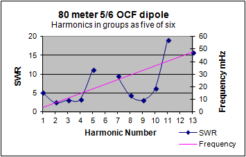
At each feed point ratio, a detailed frequency sweep was made in 0.2 MHz steps up to 52 MHz. From this, each resonant harmonic frequency was determined along with its SWR50. A regular pattern emerged. At 1/3 ratio a pattern of 2 peaks over each 3 harmonics. At 1/4 ratio, 3 peaks over each 4 harmonics, At 1/5 ratio, 4 peaks over each 5 harmonics. At 1/6 ratio 5 peaks over each 6 harmonics.
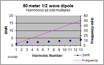
 A half-wave dipole at 3.8 MHz can be tuned to
its odd harmonics.
A half-wave dipole at 3.8 MHz can be tuned to
its odd harmonics.3. 11.6 MHz SWR 2.4
5. 19.4 MHz SWR 2.5
7. 27.1 MHz SWR 2.9
9. 34.8 MHz SWR 3.2
11. 42.6 MHz SWR 3.4
13. 50.3 MHz SWR 4.1
5. 19.4 MHz SWR 2.5
7. 27.1 MHz SWR 2.9
9. 34.8 MHz SWR 3.2
11. 42.6 MHz SWR 3.4
13. 50.3 MHz SWR 4.1
 Now you can see why 75/80 meter dipoles are
difficult to tune on other bands.
 At 1/3 ratio, a half-wave dipole can be tuned
to the first two of each
three harmonics. The SWR's are higher.
At 1/3 ratio, a half-wave dipole can be tuned
to the first two of each
three harmonics. The SWR's are higher.A 4 to 1 balun is good choice.
The antenna is 0.06% longer.
It can be bent for lower SWR matching but the improvement is very small.
At 1/4 ratio, a half-wave dipole can be tuned to the first three of each four harmonics. A 4 to 1 balun is still a good choice but SWR variance is greater.
The antenna is 0.22% longer.
At 1/5 ratio, a half-wave dipole can be tuned to the first four of each five harmonics. Few are usable.
The antenna is 0.33% longer.
At 1/6 ratio, a half-wave dipole can be tuned to the first five of each six harmonics. Only the 2nd, 3rd and 4th of each 5 harmonics are usable.
The antenna is 0.47% longer.
Dick Reid, KK4OBI at QSL.net

