
Center-fed Bent-Dipoles
Horizontal Lateral
Vertical
- OCF
Slow-Wave
Other Topics
Home
The
Three L-Antennas
Wide – Equal - Tall
A space saving antenna in the form of an upright L has been around the amateur radio world for a long time. References are found back to a QST article in the 60’s 1, the ARRL Antenna Handbook in the 70’s through 90’s 2 and to L. B. Cebik’s 3,4 and Craig LaBarge’s 5 writings in recent years. Commercial designs are seen in the Buddipole TM 5, MFJ-1790 6 and the CrankIR7 antennas. By the use of antenna modeling software10, this article is to expand our general knowledge relative to angle-of-bend and off-center-feed (OCF) configurations of the L-Antenna.
The L-Antenna
So simple.
So
easy to tune. Just hang up a wire or put
up a pole and run
another adjustable length wire or pole off to the side.
Connect your coax at the bend. It
really does not matter how you connect the
coax. It really does not matter how long is the vertical arm. Simply
tune by
adjusting the angle and length of the side arm. The total length of the
two arms
will end
up around a half wavelength. 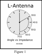 Any L-antenna can be looked at as a
center-fed dipole bent in the
middle or… a vertical monopole with a single radial.
Any L-antenna can be looked at as a
center-fed dipole bent in the
middle or… a vertical monopole with a single radial. At an elevation one-half wavelength a straight vertical dipole has about 1.6 dBi gain (deciBel isotropic). The L form however has gain around 4 dBi in the direction where the radial is pointing. Depending on ground conditions and mounting height, the impedance is around 40 ohms. This makes the configuration a decent match for 50 ohm coaxial cable.
Since the impedance of a vertical dipole is around 70+ ohms, there obviously is a 50 Ohm point somewhere between that and the 40 Ohms of an L-dipole… usually near 75° (or 15° below horizontal). Gain at this point is around 3 dBi.
Interestingly, as the arm/radial continues
to be
raised above horizontal, the
impedance
declines to around 30 ohms, the Standing Wave Ratio (SWR) approaches
2:1 but
the directional gain increases up to 5 dBi….
several times the gain of a
vertical dipole.
Off-Center-Feed
(OCF)
In computer modeling or practical
construction of a horizontal half-wave antenna, it
is observed
that impedance rises as the
feed point moves
away
from center. Resonant frequency and gain
remain the same. This
characteristic is used when matching low-impedance
antennas like a J-Pole or when using a Gamma Match or Delta Match on
multi-element beams. Commercial ground plane antennas with short
radials are
also
off-center designs.
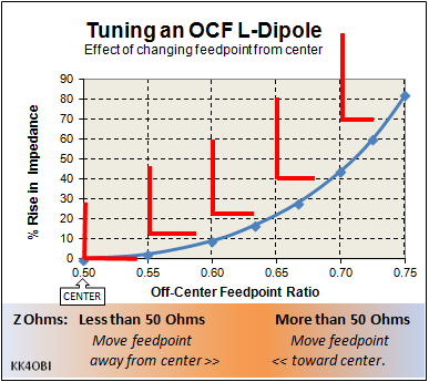
Figure 2 following is a generalized impedance graph of what happens when feeding a dipole off-center.
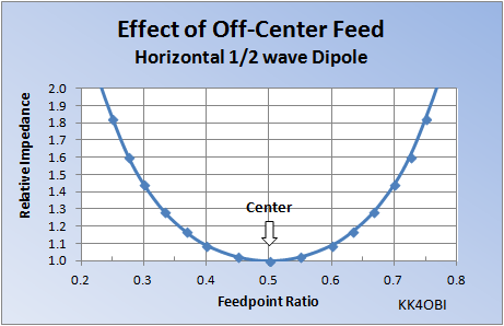
A little Off-Center there is little change in Relative Impedance.
At 0.4 Feedpoint Ratio the Relative Impedance is 1.09 greater.
Example: 37 Ohms at Center rises to 40.3 Ohms at 0.4 Feedpoint Ratio.
Farther away from Center the rate of rise increases. At 0.3 Feedpoint Ratio the relative impedance is 1.44 greater. At this ratio 37 Ohms at Center becomes 53.3 Ohms.
Note: The farther off-center, the greater the current imbalance between arms, the greater the “common mode” current on a coaxial feed line. Common mode current problems cause a change in tuning if you touch the cable, sometimes tingling or “bites” to face and lips when transmitting. RF radiating from the coax can couple with nearby electronics or power lines to affect TV and radios as well as control devices like alarms, thermostats and monitors.
Recomendation: Use a choke balun at the feedpoint.Wide,
Equal and Tall
L-Antennas
The Equal L-Antenna
With “equal” arms, a perfectly tuned horizontal arm is slightly longer
due to the effect of ground. The arm-to-arm ratio
therefore is not
exactly 0.5. Impedance is around 40
ohms. SWR can be as low as1.2 to 1.3:1. Horizontal and vertical RF polarization is
equal.
The principles of OCF apply very well for L-antennas. The Wide or Vertical characteristic can emphasized by making OCF ratios smaller or larger.
The Wide L-Antenna
As the off-center feedpoint ratio goes less than
0.5, the L-antenna becomes wider and the impedance rises.
The antenna hears and talks more like a horizontal
dipole as the SWR
approaches 1:1.
The Tall L-Antenna
As the off-center feedpoint ratio goes greater than
0.5, the L-Antenna becomes taller and the impedance rises.
It hears and talks more like a vertical
antenna
as the SWR
approaches 1:1.
Based on antenna modeling at one-half Wavelength Height, Figure 3 below summarizes the SWR and Impedance as the feedpoint is changed by 0.05 (5%) increments around the center 0.50 ratio.
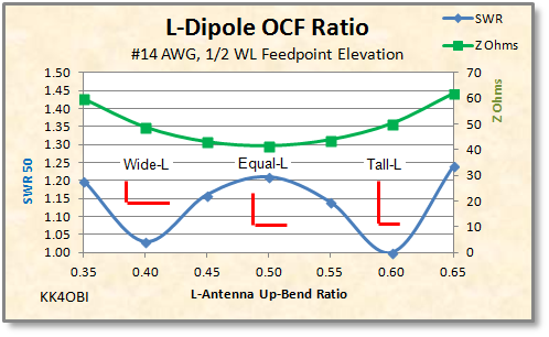
Figure 3
It is clear that an L-Antenna is easy to
tune at
any up-bend
ratio between about 0.30 and 0.65; and with effort, out to a 0.25 or
0.75
ratio. For hams wishing to fine-tune their L-Antennas, 0.40
and
0.60 are the magic points.
Note that there is an impedance effect
caused by
ground
coupling as the horizontal arm gets longer. The Wide L-Antenna can not
quite
get to a 1:1 SWR.
Of particular interest is that L-antennas
have
both
vertical and horizontal polarization. The
ARRL Antenna Book says: “Some immunity
from fading during reception can be had by using two receivers on
separate
antennae, preferably with different polarizations” 9.
In this case there are different polarizations on one antenna. The resulting effect of reduced fading can be heard on DX signals by switching between an L-Antenna and a conventional dipole or ground plane. For nearby communications, an L-Antenna makes all the difference in hitting repeaters and talking to hams using both verticals and horizontal dipoles or yagis.
The Tall-L
Antenna
When the
vertical
arm is tall, the length of a 90° side arm
length can be adjusted to resonate the antenna to the desired frequency. The SWR match of a Tall-L antenna can be
better than the Equal-L Antenna. Depending
on elevation, ground and diameter of the wires
or
tubes used,
there will be some ratio between the length of the vertical and
horizontal arms
that will give the best match to a 50 ohm coaxial cable.
According to Figure
3, with a 90° side arm: start with 0.6 Tall Ratio.
This tall L-configuration is quieter
than a conventional ground plane and performs well for DX.
It can
be a good choice when listening around the band.
It has another notable
feature. It develops a horizontal
component from the side arm. This gives
some directionality and gain over a vertical antenna.
The directionality is a bit more
broadside
to the side arm but generally semi-circular as seen in Figure 5. The angle of the side arm can be used for
tuning OCF ratios as tall as 0.75 up-bend .
Modeling
Antenna
modeling
software can optimize a vertical dipole into
the tall OCF form. Using that
capability, Figure 4 below shows
what happens to a Tall OCF dipole as the shorter lower arm is
swung
upwards in 15° increments from 0°
(down), to 90° (horizontal), to
150° (60° up). Standard conditions are: 2/3-1/3 ratio, #14 AWG, ½
wavelength feedpoint elevation, over “real ground”.
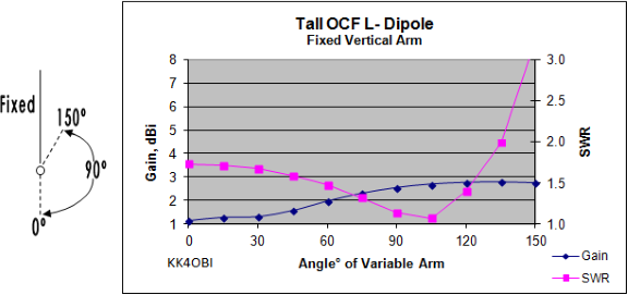
- The lowest SWR occurs with
the variable arm at 105°… 15° above horizontal.
- The gain of the Tall-L Antenna is over twice that of the OCF vertical dipole at 0°.
Model Example (Figure 5)
Conditions:
4NEC2 software10
model of a Tall-L Antenna, fed at ½ wavelength over real ground using
#14 wire,
optimized at 28.4 MHz .
Predicted dimensions:
Vertical arm: 3.147 meters tall; Horizontal arm: 2.08 meters long.
Total length: 5.227
meters at 60-40 ratio.
Impedance: 50.5 –j0.43; SWR: 1.01; Gain: 2.69 dBi
Below is the 3D view and horizontal/vertical polar graph produced by the antenna model.
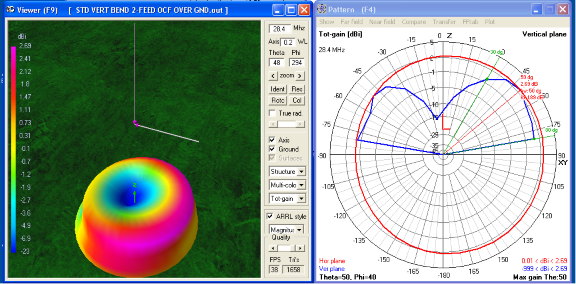
Figure 5 Tall L-Dipole
This is essentially the radiation pattern
of a vertical antenna.
Note: the radiation pattern is 2.69 dBi
stronger on the hemisphere
towards the side arm. The opposite side has 0.01 dBi gain therefore
signals are
about half as loud from the back hemisphere. Compare this with an
omni-directional 1.5 dBi circle which is the norm for a vertical
antenna.
Observe the 10-degree low angle radiation
for DX and the
slightly stronger signal at a 40-degree upward angle. No
energy is wasted skyward.
The take-off angle from 10° througn 40° is a good configuration for general,
all-around band
scanning. In addition it will hear polarized signals that might
otherwise be too weak.
The MFJ7-1790
10 meter antenna is an example. It has
an 11-foot vertical and two 6-foot radials to give “Low Radiation Angle
for
outstanding DX”.
The Wide L-Antenna
When the
vertical arm is short, the length of a 90° side
arm
can be adjusted to resonate the antenna to the desired frequency. The SWR match can be better than the Equal-L
Antenna. Depending on
elevation,
ground and diameter of the wires or tubes used, there will some ratio
between
the length of the vertical and horizontal arms that will give a nearly
perfect
match to a 50 ohm coaxial cable.
This Wide-L configuration
has the characteristic of being shorter than a halfwave dipole with
nearly the
same gain. Having both horizontal and
vertical polarization, it is less effected by undulations in DX skip
reflections (QSB) than a conventional dipole.
Antenna
modeling software can optimize for the best wide OCF ratio at
1/2-wavelength feedpoint elevation over ground.
Using that capability, Figure 6
below shows what happens with a 2/3-1/3 ratio as the longer lower
arm is swung upwards in 15°
increments.
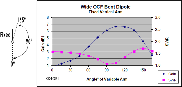
Figure 6
Note that the best SWR and Gain
combination occurs at
around 105°, or 15° above
horizontal, whereas, the shorter 60/40 ratio occurs at 90° horizontal.
Gain compares
favorably with the gain of a center-fed dipole using the same wire and
fed at
the same elevation over the same ground. SWR is lower.
Model Example (Figure 7,
below)
Conditions:
4NEC2 software
model10, Wide-L Antenna, fed at ½ wavelength over ground
using
#14 wire, optimized for 90° at 28.4
MHz.
Predicted dimensions:
Vertical arm: 2.083 meters tall; Horizontal
arm: 3.1596 meters long.
Total length: 5.243
meters at 60-40 ratio.
Impedance: 49.3–j0.12; SWR: 1.01; Gain: 5.88 dBi.
Below is the 3D view and horizontal/vertical polar graph produced by the model.
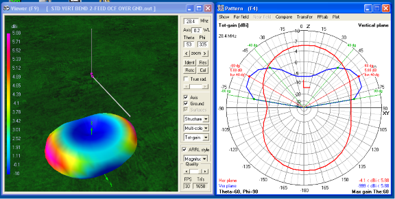
Figure 7 Wide L-Antenna
This is the radiation pattern of a half-wave dipole.
- The Wide-L antenna is directional to the side of the horizontal arm.
- The radiation pattern differs only slightly from an ordinary dipole because there is no dip on one side of the horizontal radiation pattern (polar graph, red line).
- The maximum radiation is at 30° above horizontal. Skyward radiation is minimal if feedpoint elevation is at multiples of 1/2 wavelength.
Summary
The following two graphs compare the Relative Gain and Radiation Efficiency of four kinds of dipoles, each as one of the antenna arms is adjusted through a range of angles.
1. Equal-arm Horizontal (dark line, diamond marker). 90° = standard horizontal dipole.
2. Equal-arm Vertical (violet line, square marker). 0° = standard vertical dipole.
3. OCF Tall (blue line, triangle marker). 90° = Tall L-Antenna.
4. OCF Wide (red line, X marker). 90° = Wide L-Antenna
All feedpoints at ½ wavelength elevation.
Plots stop at the point where the SWR exceeds 2:1.
OCF used is at 1/3-2/3 ratio.

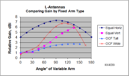
Figure 8 - Gain vs Angle
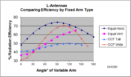
Figure 9 - Efficiency vs angle
Conclusions
- The Wide L-antenna is a shortened horizontal dipole that can come close to having the gain and efficiency of a conventional horizontal, center-fed dipole
- The Tall L-antenna performs much like a vertical but with some gain towards the side arm.
- The Equal
L-antenna is part-vertical
and part-dipole with broadside gain that can be ajusted changing the
angle of the side arm.
All three forms are suitable for limited space environments and have a degree vertical and horizontal polarization which helps in both local and long distance communication.
About Wire Antenna
Modeling
Software
This study answers the questions of what
happens when you
bend a dipole at different angles and feed it at different points.
It is unlikely an average amateur radio
operator would
have the time and resources to do this study by building prototypes
even if he
had the desire. With modeling software a
ham can do in a few hours or days what would otherwise take weeks or
months, if
ever.
The results by way of software reveal
underlying behaviour: how the changes in
an antenna affect frequency, impedance, radiation pattern and other
characteristics. Through optimization,
modeling predicts the dimensions and angles that will give the best
SWR, Gain
or Efficiency.
There is a catch. Modeling
software lives in its own perfect little world
inside the
computer. It works with the information given. The more sophisticated
the
program and the user, the better the results. In the real world we take
guidance from the results but understand there will be differences in
materials, design, construction, support structures and effects from
near-by
things.
Modeling eliminates dead-ends, gives ideas and guides us to a working antenna.
Tuning An OCF L-Dipole
References:
1. McCoy, Lewis G., W1ICP, “A Limited-Space Antenna.” QST Oct. 1960: pp. 23-25
2. “The ARRL Antenna Book.” 1974 –1997. 225 Main St., Newington, CT 06111
3. Cebik, L. B., W4RNL, “Whips, Tubes and Wires: Building a 10-Meter L Antenna.” QST Dec. 1999
4. Cebik, L. B., W4RNL, “The L-Antenna.” www.antennex.com/preview/Folder01/lant/lant.htm
5. LaBarge, Craig, WB3GCK, “The `Up and Outer` Antenna” www.qst.net/wb3gck/up_and_outer.htm
6. Buddipole, Inc. 3028 SE 59th Ct. #600, Hillsboro, OR 97123
7. MFJ Enterprises, Inc., 300 Industrial Park Road, Starkville, MS 39759
8. SteppIR Antennas,2112 116th Ave. NE, #1-5, Bellevue, WA 98004
9. “The ARRL Antenna Book”, 22nd edition, pg. 4.2.14
10. Free antenna modeling program by Arie Voors. www.qsl.net/4nec2/