
|
Navigation
Menu
Center-fed Bent-Dipoles Horizontal Lateral Vertical
Slow-Wave Other Topics Home |
This
web site is devoted primarily as a resource for amateur radio operators
to see what happens if they bend a half-wave dipole. The
performance of a dipole is highest when it is not bent. When a
half-wave or full-wave dipole is bent: the gain goes down; the resonant
length gets shorter; the frequency goes higher; the impedance
decreases. Only when the length is three or more
half-wavelengths can bending increase gain as you transition into
gull-wing, half-rhombic V and rhombic antennas.
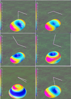
To help understand what happens to a bent dipole, you will see graphs showing the changes in Gain, Resonant Length, SWR, etc. as well as polar charts of far field radiation patterns and 3D flyover views as a bend point is moved or angle of bend changes. 1. We start with bending the ends of an ordinary center-fed dipole limited by an attic, garden, wall, etc. or to reduce turning radius. Then folding the ends back part way or into triangles. We then look at bending a dipole in the middle... up and down, side to side... to form V or L-type configurations. See illustrations of all eleven studies at: Center-fed Dipoles. 2. The second phase looks the same set of configurations but by feeding a dipole off-center, (OCF). This an outgrowth of antenna/coax matching because of the low impedance of dipoles in the V or L-form, not for multi-band application. However, as part of this, there is a study related to feed points up to the 6th harmonic and a related set of radiation patterns produced by bent End Fed Half Wave (EFHW) antennas radiating on various harmonics 3. The third phase deals with slow wave antennas for size reduction primarily for cell phones, routers, printers, remote control, as well as radio frequency identification (RFID) for merchandise or toll/parking collection- but applied to amateur radio antennas. These studies include meander, zig-zag and catenary curve methods. Other topics addressed are: Elevated Radials, Dipole Sag, Dipole Slope and Articles derived from the Bent Dipole web page. 4. The information presented is derived from a mixture of practical antenna prototyping and wire antenna modeling used to find out what is going on and "what happens if...". The software used is 4NEC2, a Windows compatible program based on an NEC-2/ NEC-4 core (Numeric Electromagnetics Code). It is used to create, view and check antenna designs and generate displays of radiation patterns. Of particular importance for the studies reported here is its optimizer function which automatically adjusts antenna variables to find the best Gain, Resonance, Standing Wave Ratio (SWR), Efficiency, Front-to-Back ratio or combination thereof. Its sweep function then graphs Far Field Radiation Pattern and 3D view plus Reflection Coefficient, Reactance, Impedance and Phase over the range of frequencies of interest. Dick Reid, KK4OBI at qsl.net |