The Z-Match Tuner
John Stewart, AA5KV
November 1, 2006
Many hams work the HF bands using a multi-band antenna fed with ladder line or some other “open wire feeder”. The old “McCoy dipole” is a good example. Lew McCoy argued1 that the simplest and perhaps most effective antenna was a random length “dipole” fed with ladder line or open wire. Provided the total length is 88 feet or longer, the antenna is reasonably efficient on 80 through 10 meters. The loop antenna is another example of a simple and highly versatile antenna. The typical loop is cut for a half wave at the lowest frequency of use. Formed into a rectangle, triangle or some other geometric shape, the loop can also be fed with open wire. Hams today are slowly recognizing that open-wire is amazingly efficient. Even with long lengths of feed line and high SWR conditions, power loss in open-wire is almost insignificant at HF frequencies. Simple and efficient…you can’t beat that!
But like everything else in life, “there’s no free ride”. First, we have the problem of routing open-wire to the shack. Unlike shielded coax, open-wire should be kept away from conductive objects as much as possible (exactly how far is debatable). For most of us, this is a formidable challenge. For others, it’s impossible and coax is the only alternative. Secondly, we have to connect the unbalanced output of our transceiver to the balanced feed line. Unless you’re fortunate enough to have a “balanced tuner”, you must make some accommodation to match the balanced and unbalanced conditions. Many hams interpose a balun between the antenna tuner (ATU or transmatch) and the antenna. Some commercially produced ATU’s designed to work with unbalanced line include an optional balun at the output. These tuners are easily recognized by terminals labeled “bal” or something else suggestive of a balanced condition. At about one-twenty-fifth the price of 7/8 inch hard-line, the extra effort to use open-wire is well worth it2.
I decided to try a McCoy “dipole” (a tuned doublet) after using a G5RV for many years. I ended up with 134 feet of wire fed with 300 ohm twin lead (slightly more lossy than 450 ohm ladder line but acceptable nonetheless). My ATU was a MFJ 901B, an inexpensive tuner that I purchased some years ago. The 901B is a good little tuner for the price. Although the 901B is a T-network, high-pass tuner designed for unbalanced line or coax, MFJ thoughtfully included a balun at the output of the tuner for use with balanced line. I was in business.
Baluns Work….Kinda
I happily used the balun inside the MFJ 901B for several months and all was well. The 901B tuned the doublet to 1:1 SWR on 80 through 10 meters. Tuning on 80 was a bit “touchy” but the match was made with several notches of inductor left to spare. The antenna seemed to work fairly well.
Around this time, I read a product review in QST Magazine of five, fairly high priced, high-power ATU’s. I was amazed at how widely they varied in efficiency3!! Most of the ATU’s were fairly efficient with a high impedance load, but efficiency fell off dramatically for low impedance loads. I wondered about the efficiency of my tuner and balun arrangement. I looked inside the 901B and saw two relatively small variable capacitors with tight plate spacing. I especially worried about the balun. The balun in the 901B looked puny to say the least and appeared to be made from high permeability ferrite material. From my reading, I gathered that a 4:1 balun did fairly well at a resistive load of around 200 ohms. But the impedance of a “tuned” doublet varies considerably over the HF bands4. Under high SWR conditions, a balun, especially those made from highly permeable materials like ferrite, tended to “saturate” and lose their broadband transformer properties. As a result, at least some of the RF is converted to heat (i.e., wasted) and in the worse case scenario, the balun could suffer a catastrophic mechanical breakdown under the large voltages associated with high SWR. Furthermore, a 4:1 balun at the output side of a tuner had a nasty habit of converting a low impedance load, to an even lower impedance load, making it less, rather than more efficient. This was exactly what led to the large inefficiencies in the ATU review described above. The solution was to use a truly balanced tuner, that is, one designed for balanced feed line, like the old E.F. Johnson Matchbox5.
The Z-match
I searched for a good, commercially produced balanced tuner. “Good” tuners, like those tested and found reasonably efficient in publications like QST Magazine, were pricey, to say the least. But after pricing the components, I understood why they were so costly. (Check a few websites for prices of “broadcast quality”, air-variable capacitors and roller inductors.) Another interesting observation is that a truly balanced, link-coupled antenna tuner is not commercially available at the present time5. At best, you can look for a used Johnson Matchbox on eBay. I have seen some with bids in the range of 250 to 450 dollars, and certainly that is an option. But another option is to build your own, like the one described in the Antenna Book (Chapter 25).
I read about the z-match tuner on several reflectors and I was mildly interested. I finally did a web search on “z match” and discovered an article by Charlie Lofgren, W6JJZ, entitled “The Z-Match: An Update”6. Charlie, it turns out, is the “dean” of the z-match tuner, having written several articles in various magazines, including two that appeared in the ARRL Antenna Compendium (vols 3 and 5). I read his web article with great interest, but it wasn’t until Phil Salas (AD5X) described his z-match tuner in the January 2003 issue of QST Magazine7 that I got seriously interested in building one. Phil’s tuner included a neat SWR indicator, which I didn’t need. My Jupiter’s had SWR metering. That reduced components and made the job even easier.
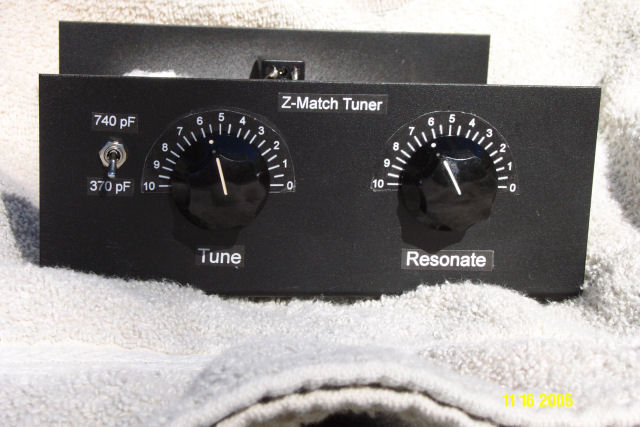
Several characteristics of the z-match project attracted my attention. First, it was simple. Without SWR metering, the tuner reduced to three basic components: two capacitors and a toroid. Second, “simple” meant relatively inexpensive. I liked that. Thirdly, there were only two components to tune, not three like most tuners. Fourth, measurements indicated that the z-match is relatively efficient and balanced to within one dB 6,8. But the Z-match tuner is NOT a truly balanced tuner. It’s best described as a “semi-balanced” tuner. It simulates an L network and remains balanced over a relatively large impedance range. But balance eventually degrades at higher frequencies, especially under high impedance loads8. Still, the z-match is probably the simplest and least expensive “balanced” tuner in existence.
I decided build a rough version of the W6JJZ z-match.
Materials
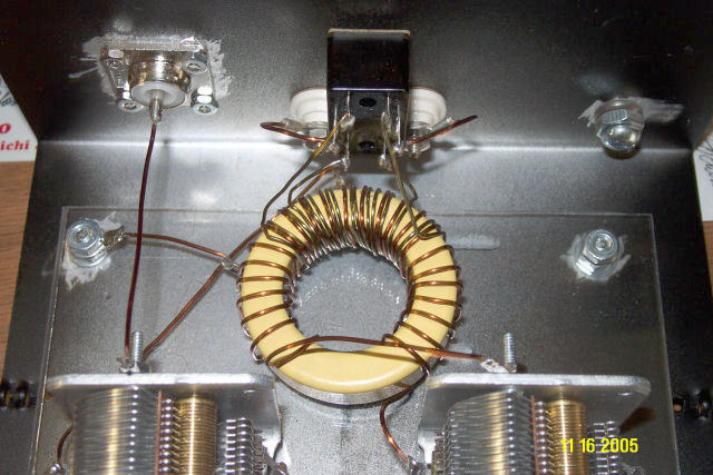
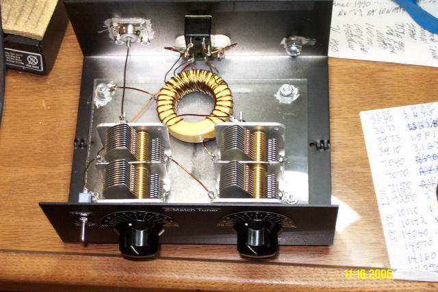
If you’re interested in building a Z match tuner, study the schematic provided by W6JJZ6. Note that both variable capacitors, C1 and C2, are not grounded, that is, they are “floating”. This has a tremendous impact on construction techniques for this tuner. Because the capacitors are “hot with RF”, you must isolate the bodies of the capacitors, as well as the shafts, from ground and from the person operating the tuner. I instinctively used a metal enclosure to build my prototype. In fact, I used a relatively inexpensive TenTec enclosure, because I’ve used them in the past with good success. But because the capacitors are “hot”, using a wooden enclosure makes more sense and those of you with good wood-working skills (not me) can come up with something functional and aesthetically pleasing. I mounted my capacitors on a Plexiglas base and brought the capacitor shafts through the front panel using rubber grommets for insulation. I felt comfortable with this arrangement, because I never run more than 100 watts. If you’re a “QRO kinda-guy” (and you know who you are), check eBay for a high-power Johnson Matchbox.
Speaking of capacitors
I had no good air-variable capacitors in my junk-box, so I search the Internet. I found an acceptable capacitor at Ocean State Electronics (www.oselectronics.com). It was a dual section air variable capacitor (BC13380), listed as 13 to 380 pf per section that could be used for both C1 and C2. The price was $22.95 and I needed two. I would only use this capacitor if you’re running 100 watts or less. If you’re likely to push the power limit, get a more substantial capacitor, i.e. one with larger plate spacing. See below for additional advice on capacitor selection.
The Toroid
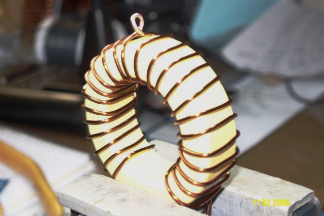
Winding the toroid is a "piece of cake", even if you’ve never done one before. I bought my toroid (T-200-6) from Amidon. Use the powdered iron toroid made from #6 material (usually colored yellow) as specified by W6JJZ. I’ve seen other z-match builders use a #2 material (usually colored red). I’m not sure it makes a difference, but Charlie claims it does. If you have a #2 toroid laying around, use it, but you’ll have to reduce the number of turns. See Charlie’s article or, if you’re interested, I’ll show you how to calculate how many turns you need. I used #18 Thermalese wire for the primary winding (I got mine from The Wireman). In the process of winding the toroid you need to make several “taps”. There are various ways to do this. Figure 1 shows the way I did it. It’s harder to describe than to do. Basically, when you come up on a turn that requires a tap, use a Dremel tool or some sandpaper to scrape off the coating for a centimeter or so, then form the uncoated segment into a loop. Using pliers, grab the loop and turn it 180 degrees, so that the free end of the loop naturally continues along the winding path of the coil.