|
2-Element-12,5-Ohm-
Yagi
with 0,40m-Boom
Complete
description of all details for building this Yagi and stacking to an array
|
Short data: Gain 4.7 dBd, F/R >20dB
Bandwidth
300 KHz (50.0-50.3
MHz) at SWR < 1.5, -3 dB hor. 66,6°, -3 dB vert. 123,4°
The antenna has an unbelievable pattern, but must have a very clear surrounding! Do not use this Yagi
in a "christmas-tree" of other antennas.
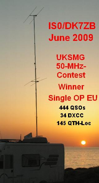
The UKSMG-Contest 2009 was
won with the stacked array 2 over 2 as you see in the picture right.
Stacked Array: Gain > 8 dBd
|
|
A 2-Element-Yagi for 50MHz
(Report in the UKSMG "Six News", Issue 96, Aug. 2008)
The
2-element-Yagi is the most effective directional antenna. One additional element
parasitic coupled with a length of about a half-wave to a dipole will increase
the gain from 0dBd to 4-5 dBd. Further 4,5 dB more gain would need a 5- to
6-element Yagi with a boom-length of 1 λ! The ARRL-Antenna-Book says about
the 2-Element-Yagi “The most bang for the buck”.
A
two-element Yagi with a director needs a spacing of 0,05-0,1 λ, the
feedpoint impedance drops down to 10-25 Ω. This makes it possible to feed a
12,5-Ω-Yagi with the very simple “DK7ZB-match”, which was introduced
first in 1995 [1]. This match uses two 50-Ω-cables with an electrical length
of λ/4 in parallel as a quarterwave-impedance-transformer with a Z=25 Ω.
The principle of the DK7ZB-match is shown down.

The two
cables are wound to a coax-choke and give a very good suppression of
screen-waves. In the meantime a lot of yagis built by hams all over the world
use this simple match with good success. For an impedance of 28 Ω the same
method can be realized with two parallel λ/4-75-Ω-cables
The
dimension of the yagi was designed with EZNEC+5 [2] for a resistitive load of
12,5 Ω and an element distance of 40 cm (0,067 λ).This gives a gain of
4,7 dBd, a F/B ratio of 17 dB and a bandwidth of 300 KHz for a SWR <1,5.
The free space patterns (azimuth and elevation) are shown in the pictures
down, the SWR-graph see above.


You must
use the exact given dimensions, the tapering and the diameters are very
critical. Other tube diameters need a new calculation!
Table
1: Lengths and dimensions of the Yagi
| |
Position |
Length 10/8
mm |
Length 12 mm |
Length
7/16''+3/8'' |
| Radiator |
0 mm |
2976 mm |
2950 mm |
2968 mm |
| Director |
400 mm |
2842 mm |
2816 mm |
2830 mm |
Building up the beam
For
lightweight portable operation I use a middle part of 2x25 cm with aluminium
tubes 10x1 mm, the outer element parts consist of 8x1mm tubes. For a more stable
construction at home it is better to use 12x1 mm aluminium (table 1)
for the full length. The given length of the radiator is from tip to tip with an
insulated part of 12 mm in the middle of the element (pictures at the end of the
site).
For the non metric tubes I give dimensions in inch in the table above.

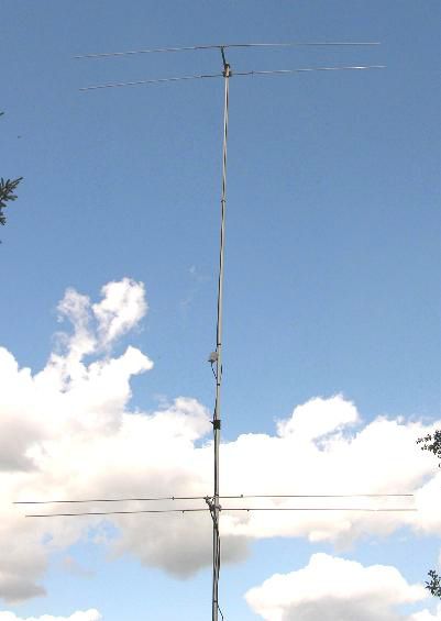
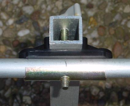
The boom
is made of 20x20x1,5 mm square aluminium, for the mounting of the director I use
TV-clamps (polyamid). See the picture above for the details.

The
impedance choke is made of two pieces of RG174 in parallel, each length
is exactly 1 m long, which refers to the screen and is λ/4*V long
(V=0,667). The construction
(picture 5) will handle 200 Wtts SSB/CW, if you will use higher power up
to 500 Wtts you must take the same length of RG-58. In that case the
choke must be mounted outside the box.
The
coax socket is grounded to the boom, this gives a better sleeve-wave
suppression than the choke alone.
Getting in the air
The
antenna with its small bandwidth is very sensitive to the surrounding, a clear
neighbourhood will be needed for a perfect working. The minimum distance to
earth is 3m, in that height you can test the antenna. The resonant frequency can
be changed by making the radiator longer or shorter. If the impedance is to
high, the director must be made longer, if it is to low, you must shorten it a
bit. The best SWR should be reached at 50.150MHz.
Stacking the Yagis
The
stacking cable is made of 2x3/4-λ coax-cable with 75 Ω, this will give
an additional SWR <1,15. The ideal resistance for the impedance would be 71Ω,
but such cable is not available. I use RG-59B/U in MIL-quality, with a length of
exactly 2x3m. For higher power each 75Ω-cable is suitable (e.g. RG-11), but
you must know the right V (velocity of propagation) for the correct 2x3/4-λ
pieces. It is recommended to test the stacking cable with two 50Ω-dummies
for correct function.
The
vertical pattern for free space is shown above. For the case that the
heights of the two antennas are 6 m and 10 m above a ground with medium conductance
I have simulated the vertical pattern in the picture below.
This configuration I have used in the 2009 UKSMG-Summer-Contest with big
results!
Meanwhile
a lot of 50 MHz-Stations in all continents use DK7ZB-designed homebrew antennas.
The principle is easy matching and good performance. If you are interested in
more 50 MHz-Yagis, please look for the other antennas on my page.
Photos
and comments for my website are very much appreciated.
References:
[1]
Steyer, M. (DK7ZB): Einfache Speisung von Monoband-Yagis, FUNKAMATEUR
(44) 4/95, S.406
[2]
Program EZNEC+5 by Roy Lewallen, W7EL, http://www.eznec.com
[3]
Homepage DK7ZB, http://www.mydarc.de/dk7zb
|
Mounting of the Director (12 mm) with an insulated
clamp and 20x20 mm-Boom
|
|