IN3OTD's web site
...under perpetual construction.

Homemade SMA male calibration kit measurements
After the not so good experience with the cheap male SMA connectors described here, I have chosen a better connector to build the SMA male calibration kit, namely the Amphenol 901-9895-RFX.
Open
Simply a bare SMA connector with the center pin trimmed down with a rotary tool the be flush to the dielectric. At the frequencies involved here the absence (or presence) of a shield around the ground pins makes no difference.


Short (SnPb solder only)
This reference short circuit was built by simply flooding the back of the connector with enough tin-lead solder to fill the void between the center conductor and ground. In retrospective, it would have been better to trim the center conductor a bit before soldering, but I was in a hurry (as usual).


50 Ω load - 2 x 100 ohm
This load was built using two Panasonic ERA-6AEB101V thin-film resistors (100Ω 0.1 %, 0805 size, 125 mW max) in parallel.


Calibration kit modeling for the HP 8753C
SMA male short model
As previously said, the HP 8753C does not allow to specify a parasitic inductance for the short as this is assumed to be zero, so only the offset transmission line parameter can be used to model this standard behavior. Here are the optimization results
| offset delay | offset loss | offset Z0 | L0 | L1 | L2 | L3 |
|---|---|---|---|---|---|---|
| 44.83 ps | 3.21 GΩ/s | 50.58 Ω | 0 pH | 0e-24 H/Hz | 0e-33 H/Hz2 | 0e-42 H/Hz3 |
Fitting results:
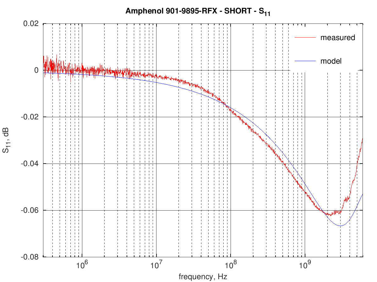
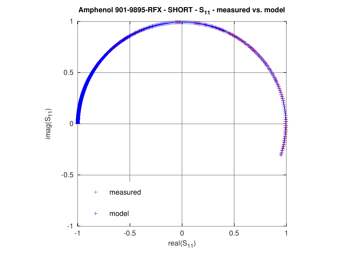
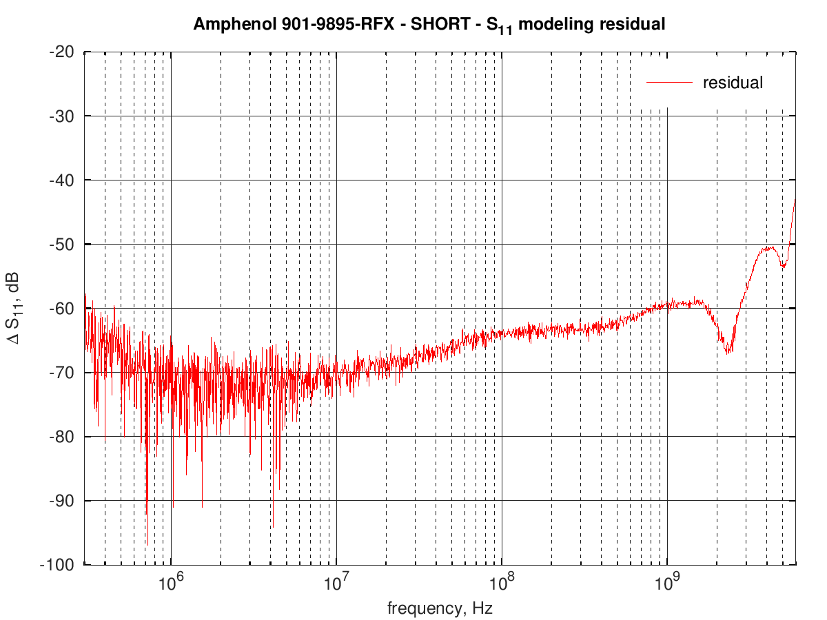
the overall RMS error is around -58 dB.
SMA male open model
The open model includes a frequency-dependent parasitic capacitance, which allows to obtain good results over a wide frequency range. In the optimization results below the offset Z0 has been optimized also, even if the connector has a 50 Ω impedance, to reduce even further the fitting error; as a result, the offset delay and impedance of the model are quite far from the actual values.
| offset delay | offset loss | offset Z0 | C0 | C1 | C2 | C3 |
|---|---|---|---|---|---|---|
| 34.04 ps | 2.62 GΩ/s | 50.0 Ω | 268.18 fF | -44.94e-27 F/Hz | 1889.24e-36 F/Hz2 | -123.58e-45 F/Hz3 |
Fitting results:
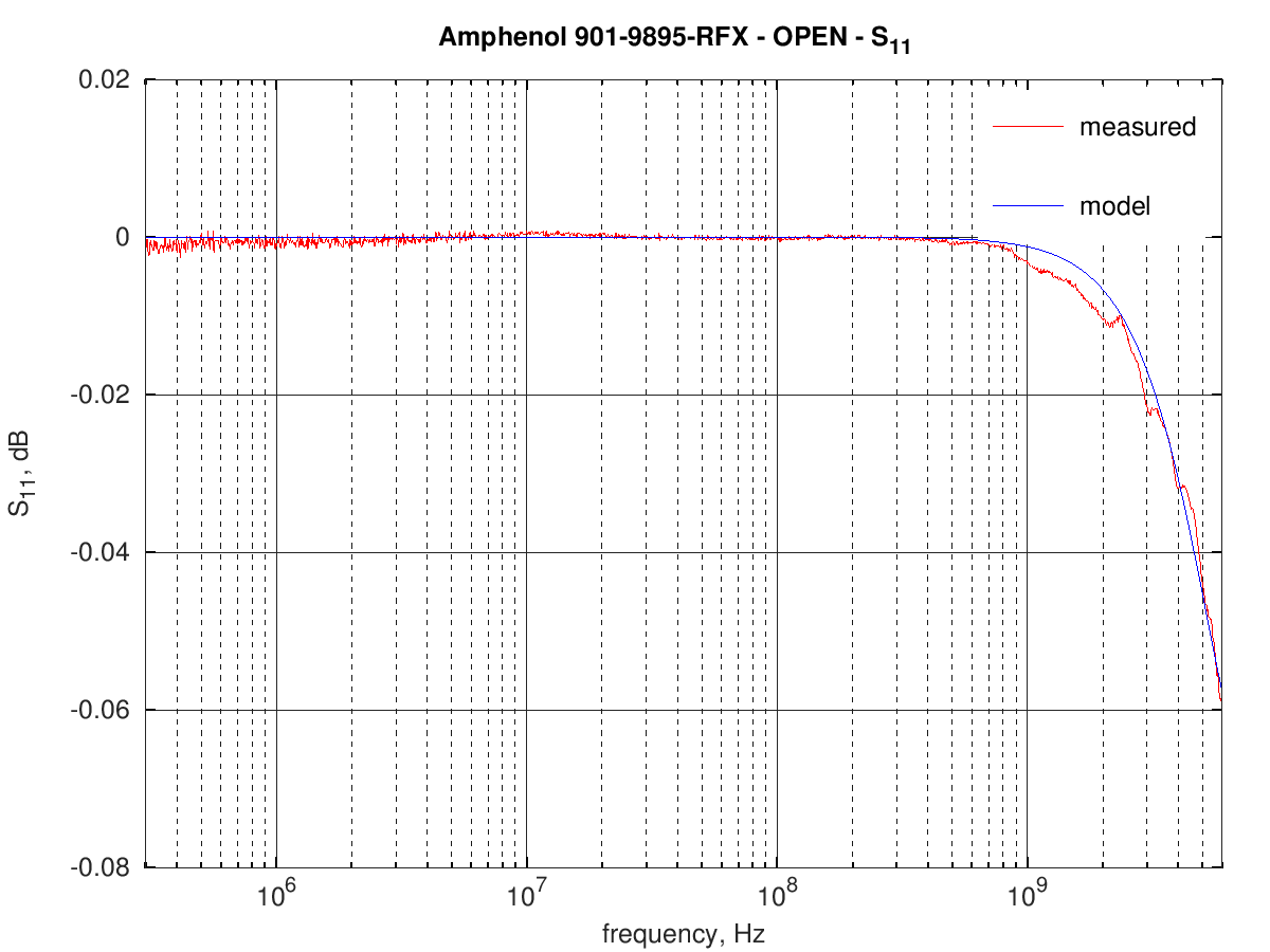
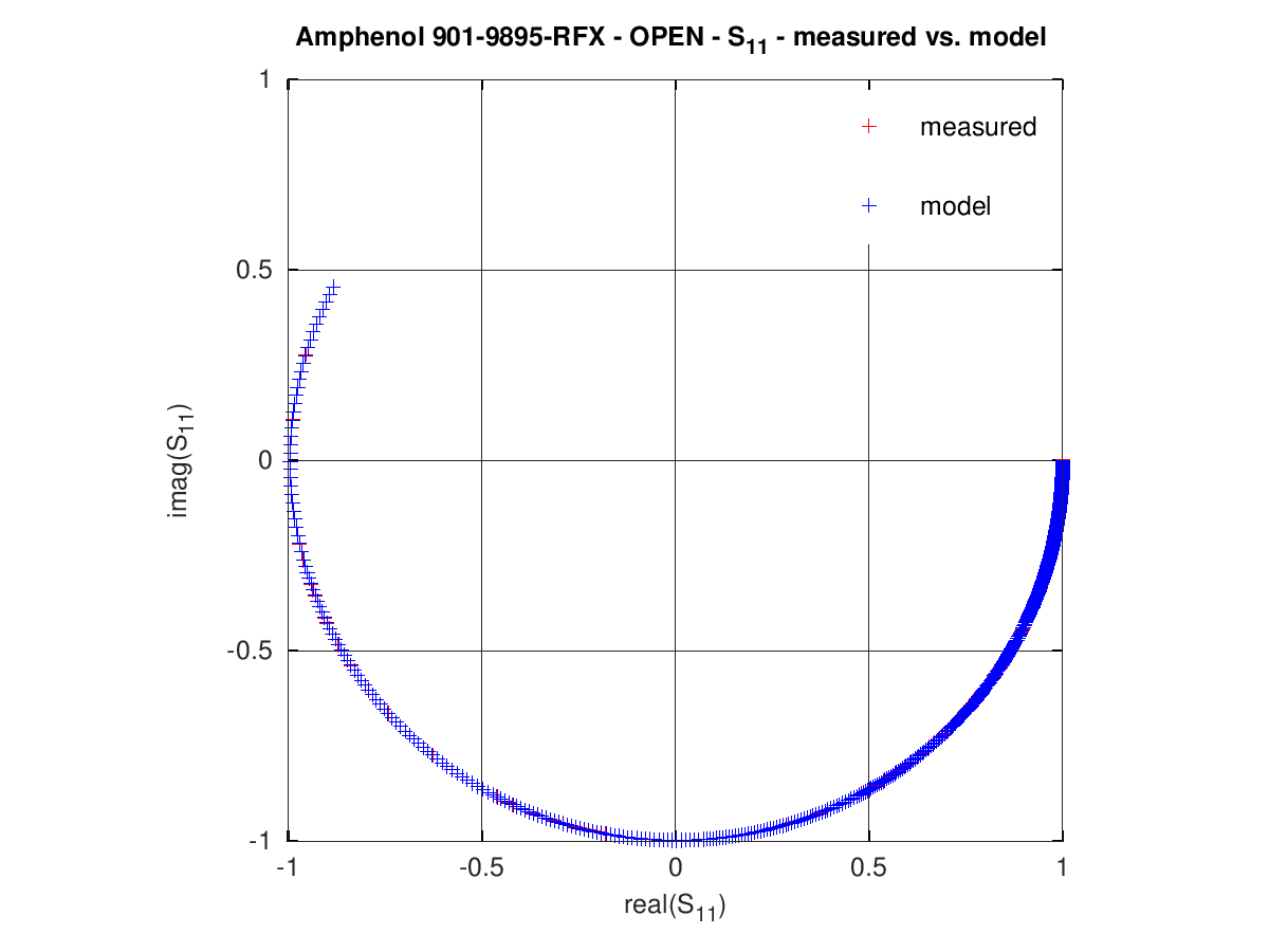
This is the residual error (model S11 - measured S11) across the whole frequency range:
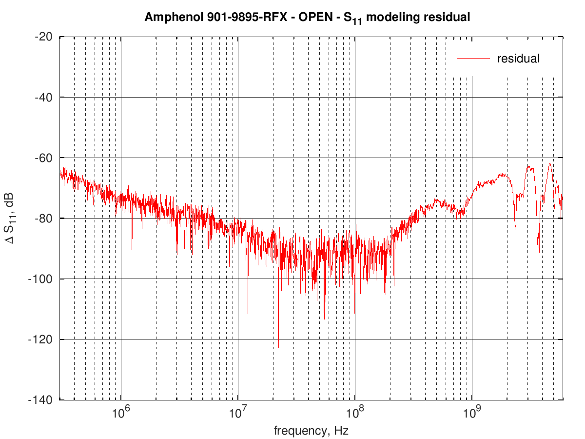
the overall RMS error is around -73 dB.
SMA male load model
The load model of the 8753C does not have many parameters that can be optimized to obtain a better fit; as a result the high frequency model behaviour starts to diverge from the actual measurements. The optimized model values are :
| offset delay | offset loss | offset Z0 |
|---|---|---|
| 91.56 ps | 0.218 GΩ/s | 50.52 Ω |
Fitting results:
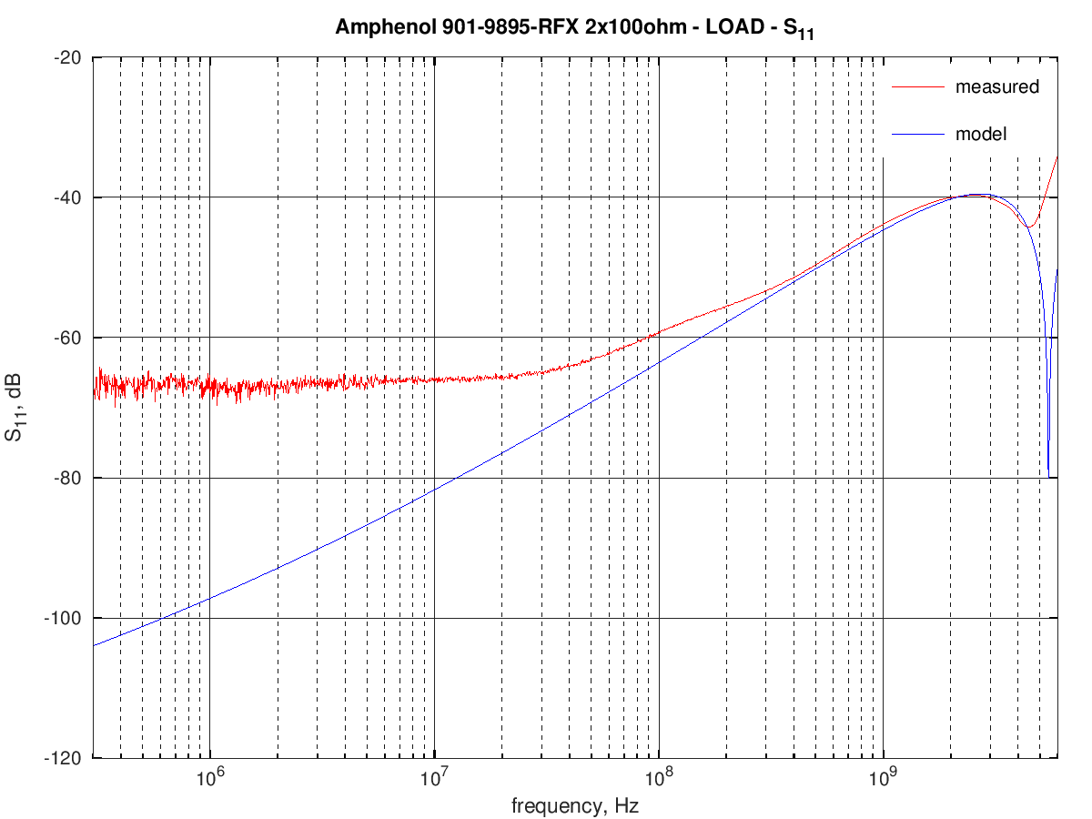
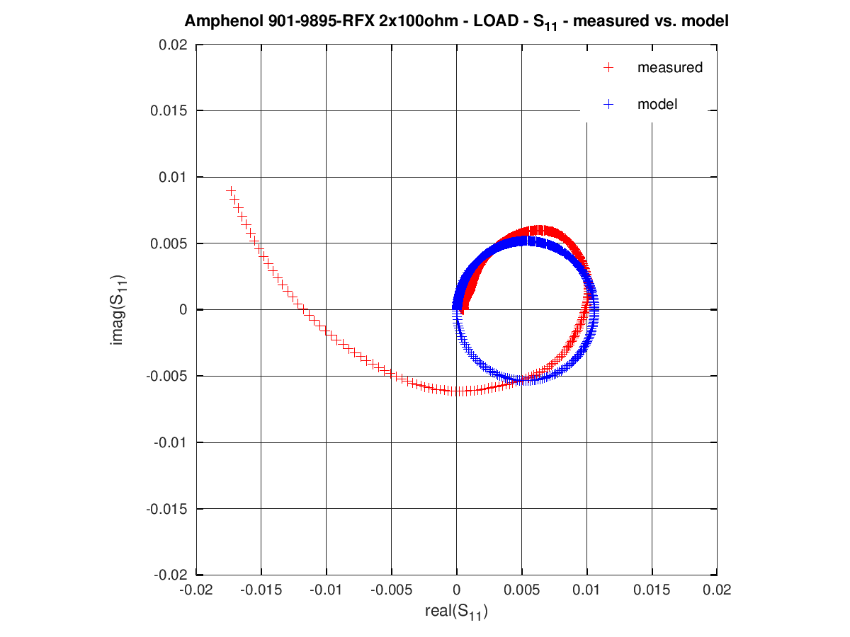
This is the residual error (model S11 - measured S11) across the whole frequency range:
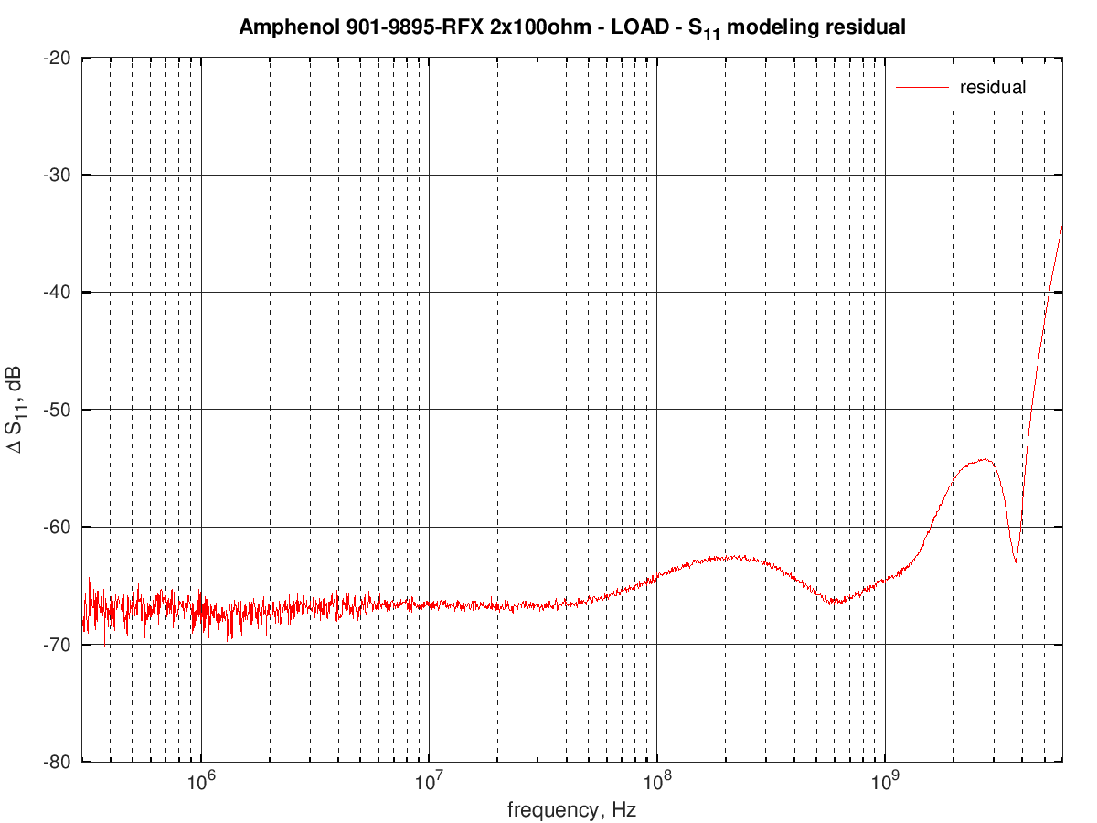
the overall RMS error is around -52 dB but the error at high frequencies becomes quite high, probably because of the parasitic capacitance that cannot be accounted for in the model.