IN3OTD's web site
...under perpetual construction.

LDMOS devices modeling
Under construction...
This page contains some notes about LDMOS devices modeling; while the concepts discussed are general, the main focus is on obtaining models for low/medium power amplifiers for the HF/VHF amateur radio bands.
At first, the small-signal model extraction is discussed and a method is presented that allows to obtain an estimate of the main parameters. The values obtained can then be used as a starting point for an optimization procedure, in order to obtain a model which fits even better the measured data provided as input. Of course, better could have different meanings, so first a measure of the model quality has to be defined; as discussed in [1] several different choices are possible.
Some practical examples of commonly used RF LDMOS are also presented on their own pages (see menu on the left): these model were optimized using the S-parameters Error Vector Magnitude (EVM) as error measure [1].
LTspice is a very popular free SPICE simulator from Linear Technology; while not specifically aimed at RF circuits simulation it can of course be helpful also in that area. For some of the most popular devices a (large signal) LTspice model based on the VDMOS device model has also been extracted; while in general its quality is not exceptional, it can nevertheless be used for a first design evaluation.
Later on also the extraction of a large-signal model, based on [5] and [6], will be presented.
Small-signal model
The following figure shows a typical MOS equivalent circuit

The Z-parameters of this equivalent circuits can be easily determined after some tedious calculations; the general idea is first to compute the Y parameters of the intrinsic part and then add the contributions of the extrinsec resistors and capacitors [2]
Assuming  the Z-parameters are
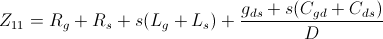
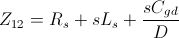
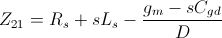
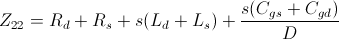 where
where

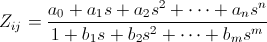
There are a number of different methods to determine parameters values of the small signal model circuit ("parameters extraction"); one of the most general is described in [2]. The Z-parameters above are rewritten as a ratio of polynomials whose coefficient can be determined by fitting these rational functions to the measured Z-parameters;
 Note that some of the Z-parameters equations may need to be multiplied by
  so that all
  are non-zero and
  .
An important feature of this method is that a least-square fit can be determined directly, without any iterative optimization needing an initial starting point close enough to the optimal values to converge properly.
.
An important feature of this method is that a least-square fit can be determined directly, without any iterative optimization needing an initial starting point close enough to the optimal values to converge properly.
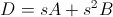
For the circuit above, still assuming , the Z-parameters are rewritten as

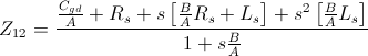
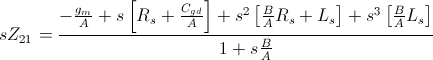
 note that the denominator of all the expressions is the same.
In the equations above
note that the denominator of all the expressions is the same.
In the equations above

 so that
To be continued...
Large-signal model
Under construction...
References: