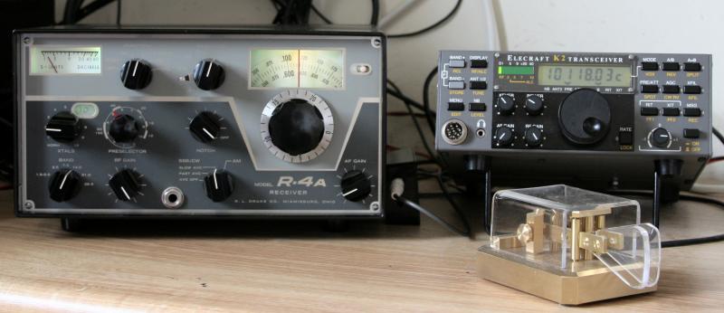
Antenna splitter to use an external receiver (Elecraft K3, but has other uses)
With the KXV3 transverter interface, the antenna feed can be looped via an external filter or pre-amplifier. I have connected an external antenna splitter to mine, the RX OUT feeds the input of the antenna splitter, one port of the splitter connects to the RX antenna in, the other to an external receiver. I use a Perseus SDR receiver to both work with CW Skimmer and also for use as an outboard receiver. The splitter can be switched in and out of operation by the K3 front panel button "RX ANT".
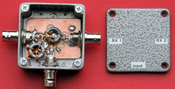
Of course, the splitter can be used for other purposes and is not restricted to being used with a K3. The circuit and measured performance of the splitter are shown below, it is designed for use between 500 KHz and 55 MHz.

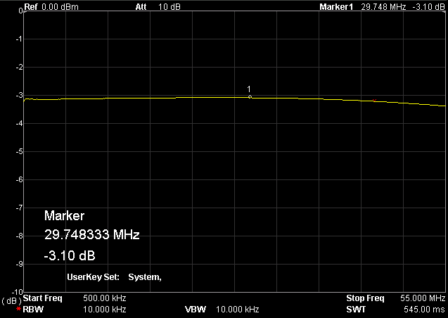
The above image is insertion loss between the input and either RX 1 or RX 2, with the other RX port terminated in 50 Ohms
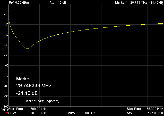
The above image shows isolation between RX 1 and RX 2 with the input termined in 50 Ohms
I previously used 8 turns for T1 and T2, there is an improvement in performance at higher frequencies when using 4 turns, around 0.5 dB less insertion loss at 55 MHz and 4 dB better isolation.
Elecraft K2 mods
Here are a couple of modifications that can be done to a K2 in order to operate it as a stand alone transmitter, and also interface it to a VHF (or UHF) transverter.
The image at the top of the page shows my Drake R4A hooked up to my K2. The R4A is being used as an outboard receiver with a buffer amplifier fitted internally within the K2, together with an external mute unit. Here is a link to the full article in Adobe Acrobat format (400 KB file size).
I used to run a Microwave Modules MMT144/28 transverter with my K2. If you would like details of the interface, attenuator and interconnections, download this Adobe Acrobat file (92 KB).
Elecraft K1 mods
The K1 is a quite useful transceiver for portable and QRP operation. It does have one or two limitations, one being a tendency for VFO drift and the other being the limited tuning range of the internal ATU. I have a couple of mods that overcome the drift and increase the tuning range of the ATU. My VFO needed up to 3 hours to settle down, although the amount of drift was close to specification it was annoying. This mod adds a Cumbria Designs X-Lock to the K1.
The ATU mod adds a couple of additional capacitors, and removable jumpers, to the KAT1 in order to provide additional capacitance on the lower bands. The links can enable the additional capacitors to be inserted or removed depending on the antenna configuration and are usually inserted when I use the 80/40 band board and removed when I use the 40/30/20/15 board.
PTT hold on circuit
My Elecraft K4D with the current firmware drops the transmitter
before the data has left the radio. This may be a problem with other DSP based transceivers. This circuit is a simple way to extend the time by around 17 or 18 mS. The Kantronics KAM Plus has a parameter to delay PTT from dropping but oddly enough SCS modems don't appear to include this parameter. The circuit is here.
ALC "Spike" modification (used with an Icom IC-7300 on 4m)
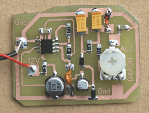
Some transceivers are prone to outputting full power when used with a linear that requires less than their full output. One solution is to input a fixed level of ALC Voltage into the radio in order to limit the output power. This solution has been used successfully with a Yaesu FT857D and an Icom IC-7300, it will probably work with other transceivers that have an ALC input level between 0 and -4 Volts. It may also be used to reduce power on older radios that have no specific power setting, although I have only used it with the FT857D and IC-7300. In the case of the 7300, the spike only appears to be a problem on the 4m band and then only on SSB.
Note, the ALC input Voltage needed typically varies depending on the band. This solution is "OK" for a single band but is not suitable for a radio that has a spike problem on all bands when running less than full power.
The NE555 is configured as a free running oscillator producing a square wave at a frequency of approximately 1 KHz. This is rectified by the 1N4148 diodes to produce a negative Voltage. There is a 4.7V Zener diode to supply a steady Voltage to the output potentiometer, the 680 Ohm resistor restricts the maximum output to -4 Volts. Capacitor C4 should be a 25V minimum rating.
If using the surface mount board layout, note that SMD tantalum capacitors have a marker on their +ve end and aluminium electrolytics have a marker on their -ve end, it is easy to mount them reversed. The resistors are 1206 size, the 100uF and 15uF I used were aluminium can types and the output smoothing were tantalum. I also used wire ended parts for the 22nF capacitor (50 V disc ceramic marked 223) and for the Zener, which was type BZX55C4V7 (500 mW Zener).
The circuit diagram is here and a board layout in Sprint Layout 6 format is here
None of the above modifications are official manufacturer modifications and are done at your own risk.


|
