|
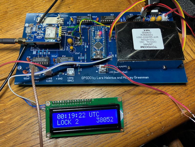
While there are low cost GPS locked, or disciplined, oscillators available from various sources, it is straightforward to make one. Examples include the entirely logic based one by G3RUH and this one by Lars Walenius and further refined by ZL1BPU. I will not include all the details, as these are covered elsewhere. However having had print boards made by JLCPCB that fit nicely into a tidy case, I will share details of the project for anyone interested in making one.
The main problem is obtaining a good ovened crystal oscillator without spending a small fortune on a new one. There are many offered on eBay from China, but their quality can be a very variable. I was fortunate in obtaining a good NEC Toyocom oscillator a few years ago.
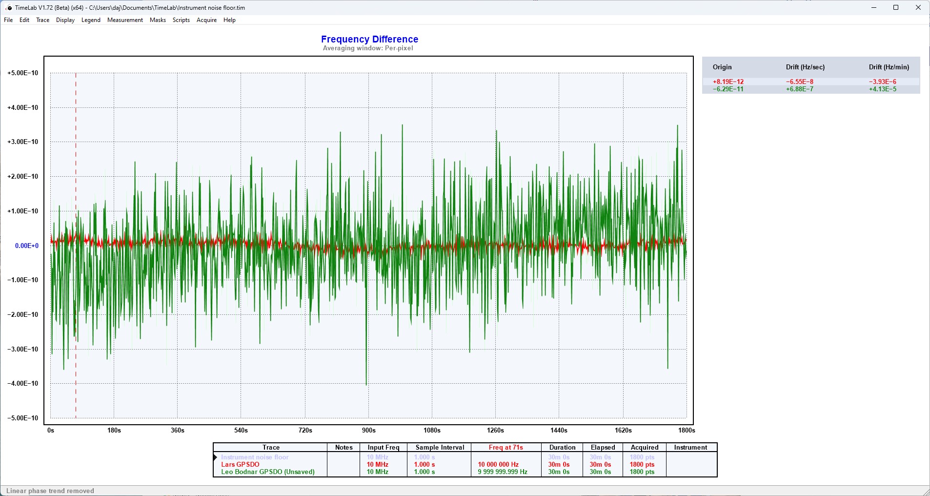
The performance of this particular unit is incredible and has around 1/10th of the short term "jitter" of a Leo Bodnar GPSDO (the original dual BNC version). The overall short term stability is not easy to measure as the only reference I have is a rubidium oscillator that may be less stable than this unit. This is a plot of this particular GPSDO compared to a Leo Bodnar one, the red trace is this GPSDO, the Leo Bodnar one is in green. The reference is a rubidium and the test instrument is a TinyPFA with TimeLab software.
By adjusting the time constant via the Arduino, a compromise between lock time and short term stability can be reached. The settings depend on the stability of the oven and the configuration is covered in the original text by Lars. The circuit needed to produce a high stability GPSDO is surprisingly simple, and uses no difficult to obtain parts. The original ZL1BPU pages include details of the Lars version and are currently still available here: ZL1BPU GPSDO
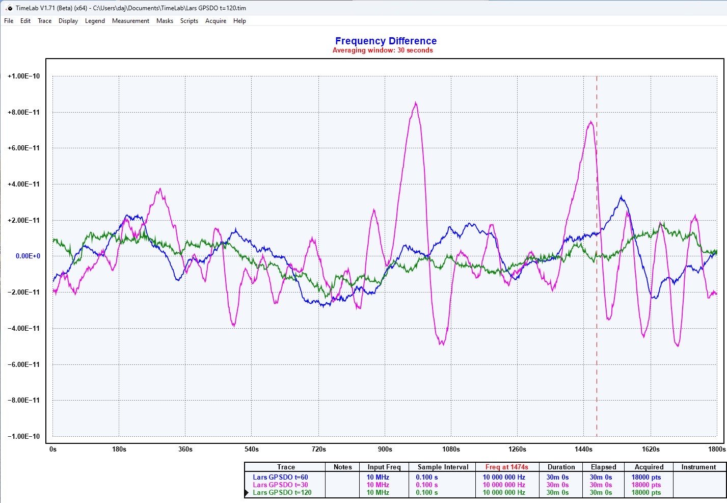
The results of using different time constants with an NEC oscillator and a Ublox Neo M8T module are shown below, the green trace is with 120 seconds and the magenta is with a 30 second time constant:
The original circuit is more or less, this one (PDF): ZL1BPU GPSDO circuit
This is the circuit of the one I built, and it is also available as a PDF: GPSDO circuit
A print board layout for the above circuits is available as a Sprint 6 layout
The Sprint 6 layout
Notes to accompany board layout for the Lars Walenius and Murray Greenman GPSDO units
The board layout was based mainly on the circuits by Murray Greenman. It was produced in Sprint Layout 6 and manufactured by JLCPCB in China.
The width of the board was chosen to fit into a Camdenboss case type CMCB00002 (CPC stock these). It is a tight fit in the case, use M3 hexagonal posts to space the board above the side fixing brackets.
Ovens
I am using an NEC Toyocom oven type TCO-6703N, which was obtained surplus several years ago. It is an SC cut crystal in an oven that takes approximately 7 minutes to stabilise in temperature. The specification is a little vague:
Supply Voltage: 12V
Power Consumption: 1A max (warm-up), 300mA typical (operating)
Output: 5V CMOS Compatible
Temperature Stability: +/-2.5x10^-9
Ageing: +/-2x10^-10 (per day), +/-3x10^-8 (per year)
Frequency trim: +/-0.3ppm (0-5V)
Most of us will be using surplus Voltage controlled crystal ovens, there are many variations of these and some experimentation may be needed. The components in the "as built" diagram are primarily intended to be used with a similar oven to that used by myself. Murray Greenman used an oven that had a supply of 12V and a control Voltage in the region of 0 to 5V. Over that control Voltage range the oscillator output at 10 MHz changed by approx. +/-7 Hz, a much greater swing than my NEC oven.
Optional components are catered for on the board to provide a separate 5V supply for a CTI type oven, these also have a similar output frequency swing to the original oven used by Murray,
Nec Ovens typically have a 12V supply and around half of the CTI oven control Voltage vs frequency change, they also have a built in frequency trim pot, in this case the 10K trimming resistor and the 47K fixed resistors can be omitted, and a link from the 39K resistor taken directly to the oven Voltage control input. This is shown in the PDF of the one I built, which can be compared to the circuits of the Lars and Greenman units, that used additional components.
The output of an NEC oven appears to be a fairly good square wave with peaks that do not drop below zero, or exceed +5V. In this case the oven can be directly connected to pin 1 of IC1. Tests with a CTI oven showed a rough square wave with significant peaks below zero and above +8V, in this case consider adding a 1N4148 diode from pin 1 IC1 to ground (cathode to pin 1) and suitable resistors to limit the Voltage swing.
GPS boards
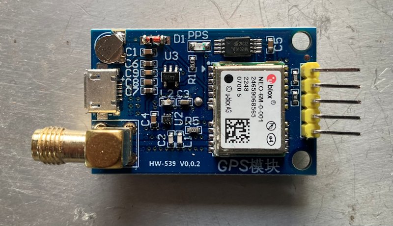
I used an eBay board fitted with a UBlox module. The GPS needs to provide a one pulse per second output and should be powered using a pair of wires directly connected to the 5V pads located near to the main 7805 regulator. Any backup battery on the board can be removed and a larger capacity backup battery, such as a CR2450 (with a series diode) used. One of these batteries should sustain the GPS module storage for around 5 years. The battery holder used was a Renata HU 2450N-1-LF from CPC. The image below shows one of these eBay boards before it was modified, note the USB socket.
Configuration of Ublox GPS modules is easy, provided you use a board that is fitted with a USB socket. On initial power up, the module will probably output 1 pulse per second from GPS satellites after satellite lock and require no changes, however the Ublox U-Center configuration software is free and is straightforward to use. If you use a timing module (such as the M8T), the location to an accuracy of around 1 metre needs to be set, the modules will run a "survey" routine to determine the position over a period of several hours, this is done using the U-Center software. Once configured, there is no need to use the USB socket again.
An alternative, and probably better, source of a genuine M8T is a complete board already fitted with one from the GNSS Store
The board fixings are for an eBay GPS board that cost less than £10, not surprisingly at this price these boards usually come with a fake Ublox Neo GPS module, often labeled “Neo-6M” or even one labeled as a “Neo M8N” that appeared as a Neo N7M in the Ublox U-Center configuration software! Buyer beware.
The mounting holes for the GPS boards that I used are M3 size, and are very close to the GPS module, I used 2mm (M2) bolts and insulating washers, the GPS board sits above the main board using 25mm long m2 bolts.
Using a genuine Ublox Neo M8T (the timing version) can provide improvements in time pulse stability, and potentially frequency stability, when used in the fixed position mode with an outdoor antenna that has a clear sky view. Another advantage of an M8T is that in fixed position mode, it will lock with just a single satellite in view, potentially allowing for a much shorter time to "lock". A genuine M8T costs around ten times the cost of a board from eBay with a fake module, removing the fake and fitting an M8T is not for the faint hearted. A cheap board with a “Ublox Neo-6M” will work and give reasonable performance at a fraction of the cost of replacing it with a genuine timing GPS module. The improvement in short term stability, between a navigation and a timing module, is that you will reduce the short term frequency wandering by around half that of a navigation module compared to the timing version, provided you use an antenna with a good sky view and have set the location accurately in the module setup.
The SMA antenna socket on the GPS board I used was removed and re-fitted at 90 degrees to allow for neater antenna cable routing if using a Camden case. The easy way to remove an SMA socket is to de-solder the centre pin, then heat the body of the socket using a large bit in your soldering iron, letting the socket drop to the bench when the solder melts. An alternative would be to mount the GPS board by its SMA socket directly to the case.
I also removed the ceramic patch antenna which is often fitted on these boards. Heat the pin on the antenna side until you are able to move it with the soldering iron bit, then using a pen knife prise the patch antenna away from the print board. There is only the pin holding the antenna to the board, plus weak glue that softens when hot.
Choice of capacitor and resistor values
The circuit by Murray used larger capacitors and series resistors, compared to the circuit originally used by Lars. Using an NEC oven, I found 10uF caps in place of the 22uF (Murray) worked OK. I haven't tried 4.7uF as used by Lars. All the resistors were 1% metal film, the 1nF NC0 capacitor was a ceramic one. My NEC oven has a trimmer to set the frequency, the adjustment trimmer on the board was not used.
Choice of IC types
74HC series of IC are used throughout, IC 1 is a Schmitt-trigger input inverter. This should ensure a clean switched input to IC2 occurs. IC4 and IC5 can be either a 74HC14 or 74HC04. Fitting the ICs in sockets is recommended. As my NEC oven outputs a square wave of 0 to 5V, I connected it directly to pin 1 of IC1, without any other components.
Board layout errors
The holes for the GPS battery connector, time setting and LCD connector are too small for the connectors I used. Do not drill them larger, in the case of the battery connector it is easy to file the corners off the connector pins to make it fit the holes. I directly connected the time setting and LCD wiring.
It may help to wire a braid directly between the Arduino ground pin (the one adjacent to D2) and the ground pin of the TIC (pin 8 of IC3).
Basic software configuration
Both the Lars and Murray Arduino “Sketches” work fine with an Arduino Nano v3. The Arduino software (Sketch) is available from the Murray Greenman site in the earlier link. I would avoid using a fake copy Arduino, only buy them from reputable sources, such as main electronic component distributors.
If using a GPS board that can be configured for multiple satellite (GNSS) networks, there is no advantage between using GPS+Galileo, GPS only, or Galileo only. I haven't used the Russian or Chinese satellites, which have poor stability compared to the USA or European ones. I use an outdoor “mushroom” GPS antenna, if using an “ice hockey puck” type of antenna on a window ledge, using GPS+Galileo may give more available satellites.
Detailed Arduino configuration
Lars produced a comprehensive set of notes on how to configure his GPSDO, the Murray version uses the same parameters.
Beware that “f2” referred to in the notes is not function key f2, but the letter f followed by 2 and <enter>. The warmup time is set by w420 <enter> for 420 seconds, etc. Save the settings by s1<enter>. All configuration is done via serial commands from the Arduino IDE program, you do not need to edit the Arduino Sketch.
Also note that you need to calculate the gain figure for your particular oven and also set the warmup time if your oven needs longer than 300 seconds to settle. The Arduino will not start to search for an oscillator lock until the warmup time is reached.
While you will obtain better frequency control using a long time constant, lock can take a seriously long time if you enter a value much in excess of the default 32 seconds. The value can be changed once lock occurs, but will then take ages to re-lock, or maybe not lock at all. My own experiments show a huge improvement in overall frequency stability using a time constant of 60 over that obtained with a time constant of 32. Measured against a rubidium standard, the stability with t=60 was within +/- 2 parts in 10^11 over a timescale of 30 minutes. By comparison, with a time constant of 32, the frequency excursion was up to 1.3 parts in 10^10.


|
