|
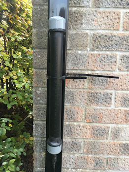
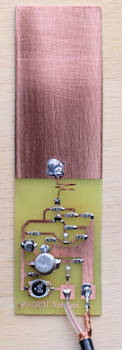
Active antennas can be very useful, in particular they can help reduce local electrical noise by allowing the antenna to be installed in a corner of the garden well away from house wiring. The original PA0RDT antenna uses a very small patch for the antenna and relies on the antenna being installed quite high. The PA0RDT uses the outer of the feeder as one half of the antenna, you can add more "patch" and less "height" for more or less the same result. Mine is installed in an 18 inch long piece of plastic waste water pipe at only 7 feet above ground. The patch antenna has had an additional piece of wire added in the form of a hair pin, nothing special, just a length of wire soldered to the print board patch.
This particular version of the PA0RDT antenna uses slightly "stiffer" bias on the 2N5109 base and more effective isolation of mains borne QRM at the DC injection (bias Tee) end. In addition there are back to back diodes and a series protection lamp, plus a transmit switching transistor to remove the supply while transmitting. The original PA0RDT antenna articles are widely available on the web.
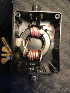
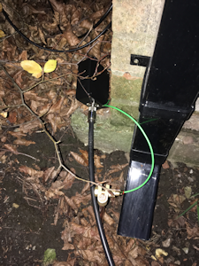
The feeder has to be grounded to an earth rod near the antenna, add a feedline choke in the coax run on the shack side of this earth rod. 12 turns of coax through an FT240-31 should keep most of the noise from the house away from the antenna. The feedline choke and the DC injection circuit must be mounted in plastic boxes to provide isolation between the input and output coax sockets. A diagram of the installation is here.
 |
 |
Construction
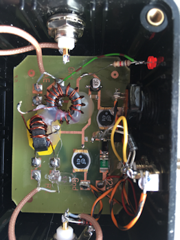
My version of the active antenna is built using mostly surface mount parts, the diagram is here. The design is not critical and there is no need to use surface mount, use whatever parts are available. The MMBT3904 is the surface mount version of a 2N3904, D1 (Schottky diode) could be replaced with a 1N4001. If you don't intend transmitting near the antenna, Tr3 and it's associated components could be omitted. Those of us who transmit will find it useful to connect one of the phono sockets to the linear keying line of the shack transceiver/transmitter... It drops the supply to the antenna when grounded, don't use too large a value for the small electrolytic capacitors otherwise the supply will not drop quickly enough.
The original bias and emitter resistors around Tr2 have been changed from the original, which results in more heat being dissipated in Tr2 - fit a heatsink to the transistor and make sure the transistor is mounted close to the board, otherwise the heatsink will foul the plastic tube the board is mounted in.
Once tested, spray the remote antenna board with print board conformal coating to protect it. My remote antenna unit fits inside 40mm PVC waste water pipe, the end caps came from eBay. Drill a small vent hole in the lower cap.
The feedline choke uses RG316 PTFE coax, which is easy to wind around an FT240 size core. Ordinary RG174 could be used, I have a few feet of RG316 that came from China on eBay and find it much better than 174 as the insulation doesn't melt causing short circuits when soldering. Seal the ends and braid with liquid electrical tape to avoid corrosion and drill a small vent hole in lower edge of the box.
A board layout suitable for use with Sprint-Layout 6 is here. Uses for an active antenna
Other than the obvious, this antenna works really well with an SDR receiver and CW Skimmer, especially a wideband receiver and Skimmer Server. In addition it makes a good low frequency receiver antenna and an alternative RX antenna for those with transceivers that have such an input. The antenna works down to a few KHz and picks up the SAQ transmitter on 17.2 KHz quite strongly, the upper frequency limit is in theory 30MHz or 40MHz, although most will probably use one on lower frequencies. The received signal strength is generally less than that from a dipole or ground plane, although the signal to noise ratio can be much better, depending on how close your other antennas are to local noise sources. In some instances the received signal is stronger on the active antenna, usually when compared to a horizontal dipole close to the ground when listening to DX stations. Unlike some active antennas, it doesn't produce noise in the form of "hiss" or "mush". There have been reports of these antennas causing IMD products in receivers when extending the "patch" antenna, this myth is the result of using receivers with lousy dynamic range, using an extended patch to an overall length of 16 inches causes no issues with my station setup.


|