Digimode Terminal
1. Introduction
To test some new kinds of (more or less) 'digital' communication modes, Spectrum Lab has a tiny built-in terminal which allows you to transmit and receive characters.
-
For 'standard' modes like PSK31 and RTTY, there are other programs out there with a more user-friendly interface ! Spectrum Lab's digimode-terminal is intended only for experimental purposes and occasional QSOs on longwave. Thanks to some friends of the LF Experimenters community for testing it.
The digimode terminal can be activated from SpecLab's main menu ('Components') or from the component window.
Contents (of this document) :
- Introduction, main menu ( with items 'File', 'Mode', 'Edit', 'Settings', etc )
- Tuning & Control
- Receiving / Decoding
- Transmitting
- Decoder Logfile
- Special modes
- Digimode Settings
- Interpreter Commands for the digimode module
- Appendix
The screen area used for some of these blocks can be modified with a 'splitter'. Move the mouse slowly between the different window areas, until the mouse cursor changes from a pointer to a splitter symbol. Then hold the left mouse button pressed and move the mouse to change the 'layout' of the digimode window.
From the menu of the digimode terminal you can select the transmission mode and other settings. Up to now, only very few modes have been implemented. Look into the "Mode" menu to see what's possible.
To transmit text, type into the "Transmit" window and start the transmitter by clicking on the "Rx/Tx" control button. You may also load text from a plain text file into the TX window (from the File menu, "Load TX Text"). While the transmission proceeds, the transmitted characters will be colored RED in the TX window. You can remove the color marks from the "Edit" menu. You can also set the "Transmission Pointer" to any cursor position if you want to repeat a transmission (also in the Edit menu).
Received characters are displayed in the "Receive" window. You can write received text into a text file from the File menu ("Save RX Text"). Some "special" modes cannot yet be machine-decoded (like slow CW) so you will have to look on the waterfall to decode them 'by eye'.
More advanced mode settings can be modified from the 'Settings' menu of the digimode terminal. Some 'special' transmission modes are described later in this document.
To monitor multiple stations or channels, you can open up to four digimode terminals from Spectrum Lab's main window, with different settings for each terminal (as far as the bandwidth of the receiver's IF filter permits, and the CPU in your PC). To duplicate the settings from an already opened terminal window, select Settings .. Clone these settings ... from the terminal's main menu.
See also: Spectrum Lab's main index, 'A to Z', Time signal decoder (DCF77).
2. Tuning aids in the digimode terminal
There are just a few tuning aids in the digimode terminal. The most important 'RX' tuning aid is the spectrum display in Spectrum Lab's main window. If you right-click into the frequency display, a popup-menu will open with the option "set digimode frequency to xxxx.x Hz". Selecting this option sets the RX- (and also the TX-) frequency. This even works if the input is not coming directly from the soundcard but from a previously recorded wave-file !
For most digital communication modes, there is a so-called 'tuning scope'. This is especially useful to set the RX-frequency for all PSK-modes (phase shift keying modes, for example PSK31). Right-click into the tuning-scope to see all available options.
 The 'Bit Phase
Vector' display is an indicator for the phase-difference between two received
bits (or symbols) for all PSK modes. If the RX-frequency of a BPSK-signal
(like PSK31) is properly tuned, the vectors should show a vertical line (only
0° and 180° phase difference). This scope screenshot shows a properly
tuned (but very noisy) PSK31-signal.
The 'Bit Phase
Vector' display is an indicator for the phase-difference between two received
bits (or symbols) for all PSK modes. If the RX-frequency of a BPSK-signal
(like PSK31) is properly tuned, the vectors should show a vertical line (only
0° and 180° phase difference). This scope screenshot shows a properly
tuned (but very noisy) PSK31-signal.
Note that the bit-phase vectors only run from the center upwards (angle about 0°) and downwards (angle about 180°). The length of the vectors depends on their amplitudes. If the vectors are not running vertically, you should either turn the AFC (automatic frequency control) on, or try to adjust the "RX-frequency" manually.
 Alternatively,
the tuning scope can be switched into Y(t)-mode with an optional long persistance
(like an analog storage oscilloscope), which can be used to produce an
"eye-pattern" diagram because the scope is usually triggered by the receiver's
bit-synchronisation module.
Alternatively,
the tuning scope can be switched into Y(t)-mode with an optional long persistance
(like an analog storage oscilloscope), which can be used to produce an
"eye-pattern" diagram because the scope is usually triggered by the receiver's
bit-synchronisation module.
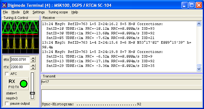
The screenshot on the left shows the "eye pattern" of an
MSK signal (actually a DGPS beacon).
The upper (green) curve is the filtered bit signal (for MSK: the frequency
deviation), the lower (red) curve is the amplitude which should ideally be
constant for an MSK signal. The eye pattern only
works for certain modulation types like BPSK and MSK.
Some demodulators will additionally show a third curve in the tuning scope
in yellow colour; for example the MSK decoder shows the recovered bit clock
(subject to change).
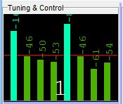 When the DTMF decoder is active, and the tuning scope mode set to 'auto',
the scope shows a bargraph with the amplitudes of the eight DTMF tones, ranging from -100 to 0 dBfs.
When the DTMF decoder is active, and the tuning scope mode set to 'auto',
the scope shows a bargraph with the amplitudes of the eight DTMF tones, ranging from -100 to 0 dBfs.
The red line in the background shows the DTMF decoder's squelch level,
which can be adjusted with the slider on the left side. As shown in the screenshot
on the left side, the squelch level should be set high enough (well above the "noise level")
to avoid false detections.
Like some other parts of the digimode terminal window, the size of the tuning scope can be adjusted by moving the light blue coloured 'splitter' controls (press and hold the left mouse button on a splitter control).
3. Receiving with the digimode terminal
3.1 Receiving text (normal, in real time)
If the "RX/TX-switch" is in the "RX"-position, and the demodulated signal exceeds the squelch level, all decoded characters are printed into the "RX"-window (which is -in fact- a windows edit control).
The RX window will automatically start to scroll the received text as long as it has the 'focus' (that is, the blinking cursor is in the RX window. Just click into the window).
You can also save the received text in a text file. Use the entry "Save Rx Text" in the File menu of the digimode terminal for this purpose.
3.2 Decoding bitstreams from 'raw files'
This feature can be used to analyse raw bitstreams (demodulated, but not yet decoded) archived in files.
These 'raw files' are not binary files, but ASCII files ("textfiles") with contain the following characters:
- 0 (figure zero) : pass a 'low bit' to the decoder, as if it had just come out of the demodulator;
- 1 (figure one) : pass a 'high bit' to the decoder, as if it had just come out of the demodulator;
- 2..0, a..f are reserved for future use, where one symbol (from the demodulator) contains more than one databit .
- Ø (slash-zero) is treated the same way as the zero, because Spectrum Lab's digimode terminal emits these characters by default
-
( ) : Everything between an opening and a closing parenthesis is ignored
by the file parser;
because for example the DGPS / RTCM decoder emits hexadecimal codes in parenthesis (even if set to 'binary' character display).
Since everything in parenthesis ignored, this can be used to embed comments in such 'test files'.
To record raw bitstreams in this format, either set Digimode
Confiuration ... Code Set to "Unknown (emit ones and
zeroes)";
or (at least for the DGPS decoder) leave the
Code Set as it is (for example, RTCM SC-104 (DGPS) ),
but under Advanced Settings, set the Rx Character Display
to Binary (ones and zeroes). In the latter case, the demodulated
databits will still be passed to the decoder, so the decoder will attempt
to synchronize frames (which is helpful because it inserts a CARRIAGE RETURN
character after each frame), but the text in the 'Receive' window will still
be filled with ones and zeroes (mostly). As noted above, almost any decoder
will put additional info between parenthesis, so they can automatically be
filtered out while analysing the file.
After receiving a sufficiently large number of 'raw bits', stop the decoder (or at least pause the display), and export the text in the receive window as a text file (through the terminal's File menu).
You can then let the saved file run through the decoder over and over again, trying different decoding (not demodulation) parameters.
To interrupt the file analysis (because the file is too large, and/or decoding takes too long), press and hold the ESCAPE key.
4. Transmitting with the digimode terminal
In most cases, plain text is transmitted with the 'digimode terminal'. In certain modes (for example Hellschreiber), small images can be sent, too.4.1 Transmitting text
To transmit characters with the digimode terminal, set the cursor into the 'TX window' (by clicking into) and just type the letters you want to transmit. If the RX/TX-control button shows "TX" and the 'LED' is colored red, the typed characters will be transmitted almost immediately.
The transmitted text will be colored red. The text which is not yet transmitted will be black (usually).
A few tips for using the digimode terminal for sending text:
- To set the transmit position to the current cursor position, press F3 .
- To send the text in the TX-window again, place the cursor before the first character you want to send, and press F3 afterwards.
- To clear any text which may be contained in the TX buffer (but not sent yet), press F2
- To switch from TX to RX, press F9 .
- To switch from RX to TX, press F10 .
- You can configure the terminal to begin TX automatically (as soon as there is something to send), and to switch back from TX to RX when all is sent. This option is highly recommended for all "slow" modes ! ( avoids overheating the transmitter when the operator falls asleep ;-)
-
DO NOT TYPE OR SEND EVERYTHING IN UPPER CASE. IT LOOKS AS IF YOU WERE PERMANENTLY
SHOUTING. THAT'S A BAD IDEA, AND AN AWFUL WASTE OF TIME.
Especially in PSK 31 (and its variants) sending everything in upper case is stupid, -even though often seen on the bands- because PSK 31 & Co use Varicode, which uses less bits for lower-case characters than for upper case. Please tell this to your PSK31-QSO partner on shortwave, maybe he just doesn't know ;-)
You can start the transmission before typing any text in the TX window - this is ok for *most* character-based modes. Alternatively, you may type your next message text into the TX window before switching from receive to transmit. This will avoid 'gaps' in the transmitted data stream (which would be filled with 'idle' characters automatically, except for Morse transmissions).
Special functions can be embedded in the transmitted text, enclosed in angle brackets. Some examples:
- <chr(123)>
- Inserts a character with the specified code in the character stream
- <img filename.bmp>
- Inserts an small image from a windows bitmap file in the transmission. Only works in Hellschreiber mode.
- <!any_interpreter_command>
- Allows the execution of any interpreter command, embedded in the transmitted text. More details and a few examples are here .
(Other commands in angle braces may exist, which have not been documented yet ... )
4.2 Transmitting images in "Hellschreiber" mode
You can also send small bitmaps along with the normal text, using a "tag" (kind of command-sequence, similar to HTML) in the text you enter (or copy into) the transmit text box. The syntax for sending an image from a bitmap file is:
<img MyFile.bmp>
The command will not be parsed as long as you didn't type the closing angle bracket (final ">"). Example for a transitted message which contains a bitmap:
TEST: <img dl4yhf.bmp> OK ?
A list of all "tags" which may be embedded in the transmission-text (can be loaded from plain text files), some of them may be abbreviated:
-
<rev>, <r> - switches from "normal video" to "reverse video" (caution, requires more average transmitter power)
-
</rev>, </r> - switches back rom "reverse video" to "normal video"
-
<img filename>, <i filename> - loads an image from a bitmap file, and places it in the Hell-transmission-buffer (inceasing the size of the "bluescreen" if necessary).
- Note:
- The BACKSPACE key does not work properly when deleting these "tags" from the transmit buffer, if the associated function has already been executed (and the result is visible in the hell transmission bitmap). BACKSPACE only works for normal transmitted characters in HELL mode !
5. Decoder Logfile
For beacon observations and other long-term surveys, the decoder output (characters) can be logged to a textfile, in addition to the output in the RX window .
To start logging, select File .. Start logging decoder output in the terminal's menu. If the file already exists, new characters are appended to the end.
To stop logging, select the same menu item again. While logging is active, it shows 'Stop Logging' along with the filename currently being logged.
Note: Each of the four(?) terminals must use it's own logfile. For technical
reasons, it is not possible that all decoders write their output into a common
file.
Because of that, the default filenames (visible when opening the fileselector
for the first time) are
'Term1.txt' for the first terminal window, 'Term2.txt' for the second terminal,
etc .
6. Special transmission modes
6.1 Hellschreiber ("Hell") Transmissions
Compared with "true" digital transmission modes, HELL is a bit different. The original Hellschreiber (invented by the german inventor Rudolf Hell) was a character-transmitting and -receiving machine, with a typewriter-like keyboard.
On the first look, the digimode-terminal works like that. You enter text in the transmit window, which will be "printed" into the blue strip in the upper part of the transmit window. But what is really transmitted are no characters, but small (narrow) images ! For optimum performance, there is a special character set (called "SMT Hell") which is optimized for best readability - but its up to you which of the various fonts installed on your system you want to use.
- Note:
- Due to problems with the installation script under Windows XP, the SMT Hell and some other "special" fonts are no longer installed automatically. If you need them, you will find these special fonts in the "Goodies"-directory. Install them with the windows system control ("Fonts", on a German PC: "Schriftarten".."Datei".."Neue Schriftart installieren").
6.2 Minimum shift keying
Minimum shift keying (MSK) can be viewed as binary, continuous-phase frequency shift keying with a modulation index of 0.5 (frequency shift divided by bitrate). Some of its properties are...
- compared with classic FSK like "RTTY", it consumes less bandwidth
- an MSK signal has a constant envelope waveform (because it's a special form of FSK)
- in contrast to amplitude-shaped BPSK (like PSK31), it does not require a linear transmitter, and does not get "broad" like PSK31 if the transmitter is overdriven (a fact which can be seen on shortwave quite often, despite the fact that radio amateurs use "linear" power amplifiers there).
For initial MSK tests on longwave, use one of the predefined "MSK" modes from the terminal's menu. They use the VARICODE set (as designed by Peter, G3PLX, for his famous PSK31 mode). But since there was only little interest in using MSK on air (among radio amateurs), I didn't develop the decoder any further (it's still implemented in SpecLab, but it's not optimized). Some notes on the implementation of the MSK modulator/demodulator can be found in the appendix, especially about the encoding scheme when transmitting VARICODE via MSK.
MSK is in worldwide use for DGPS beacons on medium
wave (near 300 kHz). See this extra document with details on
DGPS reception with Spectrum Lab's digimode
terminal.
6.2.1 MSK-modulated DGPS beacons on medium wave
To test the MSK demodulator, the author tried to receive some European DGPS
beacons on medium wave. Many of those beacons (like the Zeven DGPS transmitter
on 303.5 kHz) use 100 bit/second, so the 'symbol rate' in the digimode
configuration dialog must be set to 100.0 symbols/second (here, the same
as 100 bit/second). The parameter 'Frequency shift or span' doesn't matter
for MSK, because the shift is dictated by the symbol rate (remember, shift
divided by bitrate is always 0.5 otherwise it wouldn't be MSK..). The
eye pattern on the tuning sope looked promising,
but due to the lack of an RTCM SC-104 decoder, the codeset parameter
in the digimode configuration had to be set to 'Unknown / Emit '0' and '1').
Not too impressive. The price of 40 or 50 dollars for the official RCTM SC
104 V2 standard ("RTCM Recommended Standards for Differential Navstar GPS
Service, Version 2.0") sounded a bit steep for this experiment. Fortunately,
looking around revealed some info (without paying $$ to the moneymakers)
about how to calculate of the 6-bit checksum in each 30(!)-bit "GPS words",
so the digimode terminal can at least break up the continuous stream of "zeroes
and ones" (from the MSK demodulator) into "GPS words" and check the 6-bit
parity in each word.
A decoder for the most common DGPS message types (as defined by RTCM V2.x)
is implemented in Spectrum Lab - details are in another document.
To select between different formatting options (for the decoded output),
select Settings .. Advanced Settings in the terminal's menu, and
set the Rx Character Display option to Translated (type 1)
or Translated (type 2). 'Type 1' will show the DGPS signal as 30-bit
GPS words, with an indicator for the parity check (*=parity check ok, -=parity
check failed). 'Type 2' may present the output in a different format, which
wasn't clear at the time of this writing yet.
What to avoid (when transmitting MSK)...
Even with MSK, the transmitter must not be (severely) overdriven ! If the transmitter is modulated with an audio signal (AFSK), overdriving the audio stages may cause audio harmonics. For example, a 1 kHz audio "carrier" may produce 3, 5, etc kHz (sometimes also even harmonics). If these unwanted audio frequencies are inside the IF amplifier passband, they will produce unwanted RF emissions !
When overdriving a "linear" amplifier with insufficient harmonic suppression, you may even transmit on a "band" where you shouldn't be heared, so be careful. Don't use cheap solid-state power amplifiers without good low-pass (or bandpass) filters. Of course, this hasn't got much to do with MSK..
7. Digimode Settings
7.1 Basic Settings
Because the 'digimode terminal' has been implemented to **TEST** new communication modes, it has a lot of adjustable parameters which are usually unneccessary (because they are 'fixed' in other programs). More settings can be found on the 'Advanced settings' and 'RX/TX-Switching Options' - tabs, which are described later.
The following settings may be modified from the 'Settings' menu. Sometimes the digimode terminal automatically opens this dialog, especially after you change to an 'experimental' mode which has not become a standard yet. However, a set of 'standard' digital transmission modes can be selected from a list (click on the "Standard Modes" button in the dialog window).
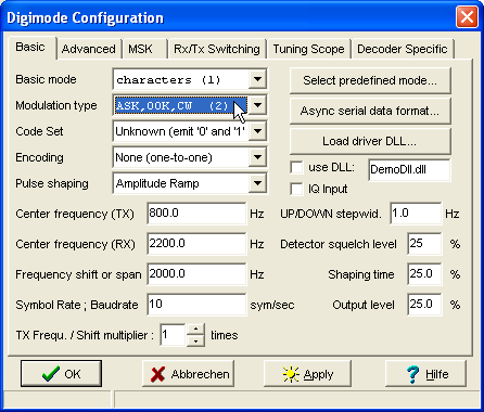
(screenshot of the 'digimode configuration' dialog, 'basic' tab)
Some parameters which may need explanation:
- Basic mode
- Defines if the "mode" is based on the transmission of single characters, blocks, or other specialities (which is the main usage of this terminal). Some of these modes are not completely digital at all. There are:
- Character-based modes like PSK31, MSK31, Morse(transmit only)
- Block-oriented modes (not implemented in SpecLab itself)
- HELLSCHREIBER-modes, here: with very narrow bandwidth. Named after the german inventor Rudolf Hell. Actually an image-transmission mode which looks like a mix between RTTY and slow-scan-television. The implementation in Spectrum Lab can actually be used to transmit small images (bitmaps) as well as characters entered in the transmit-window. Read this chapter for details.
-
- Modulation type
- This is the principle how the digital information (bits, symbols) are transformed into an analog signal. Common modes are:
- AFSK = audio frequency shift keying, used for RTTY and DFCW (not yet implemented).
- BPSK = binary phase shift keying, uses two different phase angles (0° and 180°). One symbol carries one bit of information. Often used together with the VARICODE code set.
- QPSK = quadrature phase shift keying, uses four different phase angles (0°, 90°, 180°, 270°). One symbol can carry two bits of information.
- MSK = minimum shift keying (can be regarded as a special form of OQPSK, but also as FSK with a modulation index f_dev/f_bit of 0.5). Please note that the MSK demodulator in Spectrum Lab is far from being perfect ... but at least the non-coherent decoder works, and is more robust than SL's coherent decoder. Read this chapter for details on MSK .
-
CW or OOK = continuous wave or on/off-keying. Usually used for morse code
transmissions.
-
Parallel MT = simultaneously transmitted "multiple tones", like DTMF (telephone touch-tones).
Requires a linear transmitter.
For very "special" Modes, there may be an extra "Digimode-DLL" somewhere.
- Code Set
- The code set describes how the bits in a single character are arranged before transmission. Some supported code sets are:
- Morse = codeset for telegraphy transmissions in "CW".
- Baudot = a 5-bit-code which was very common for RTTY transmissions in the 'old' days of radio. May be implemented in a "Digimode-DLL" somewhere.
- ASCII = american standard code for information interchange. Used internally by many computers, especially in the good old days. Nowadays replaced more and more by the ANSI, a very similar codeset which uses 8 bits, and contains many special (national) letters which did not exist in ASCII.
-
PSK31 'Varicode' = a code set with variable bit lengths. Frequently used
letters have shorter codes than longer letters. This nice mode was introduced
by Peter Martinez, G3PLX. It is widely used on shortwave by radio amateurs,
but also some longwave experimenters used it with good success. In Spectrum
Lab, you can use Varicode also with other modulation types than BPSK and
QPSK, and at higher and lower speed than the original PSK 31. And please,
DON'T SEND ALL IN UPPER CASE - especially not in PSK 31 because upper case
letters take much longer to send than lower case letters.
-
DTMF = 'touch tones' :
                   | 1209 Hz | 1336 Hz | 1477 Hz | 1633 Hz
          ---------+---------+---------+---------+---------
           697 Hz  |    1    |    2    |    3    |   A
           770 Hz  |    4    |    5    |    6    |   B
           852 Hz  |    7    |    8    |    9    |   C
           941 Hz  |    *    |    0    |    #    |   D
The key's column (on an old-style telephone keypad) selected one of the 'high tones', the key's row selected one of the 'low tones'.
DTMF tones are still useful today for 'remote control' over an analog audio link, for example to control a remote receiver, transmitter, antenna switch, rotor, etc.
Spectrum Lab can generate any sequency of DTMF tones, either via the digimode terminal or by command 'digimode.tx( <string> )' .
With the tuning-scope display mode set to 'auto', the scope shows a bargraph diagram with the eight tone levels (logarithmic scale, -100 dBfs to 0 dBfs).
- Encoding
-
Encoding means how 'data bits' Xi are mapped to the actual transmitted symbols
Yi. For example, consider a binary frequency-shift keyed signal:
Without special encoding (Yi = Xi) zero-bits would result in frequency A being sent, and one-bits would result in frequeny B. For FSK signals, this is almost always the method of choice.
Differential encoding is often used with phase shift keying (PSK) so simplify the data recovery at the receiver. In this case, the transmitted symbol Yi is the result of an exclusive-OR combination of the previously transmitted symbol Y(i-1) and the data bit to be transmitted (Xi). The result is that the 'polarity' of the received bits doesn't matter (i.e. it doesn't matter for a BPSK signal if the receiver is set to USB or LSB), because the receiver (decoder) only checks if the received symbol is different from the previous symbol (in that case the data bit is a ONE), or if it's equal (then the data bit is a ZERO). For some modes (like PSK31) differential encoding is always active, regardless of the state of the Encoding option.
- Pulse Shaping
- Pulse shaping is often required to reduce the bandwith of the transmitted signal. Generally, the bandwidth is reduced if the transition from one symbol to the next is 'smoothed'. There are several ways of how pulse shaping can be done:
- off: means no pulse shaping at all (->broad rectangular pulses)
- amplitude ramp: the optimum, used for PSK31, but requires a linear transmitter or a class C/D transmitter with pulse shaping via the power supply voltage (as used by a well-equipped LF amateur). See advanced settings.
- slow phase transition: not as good as 'amplitude ramp', but can be used for class-C transmitters because the amplitude of the modulated signal is constant. This shaping type is currently still 'under construction'.
- Frequency Shift
-
This parameter is only required for FSK (frequency shift keying) modes like
RTTY and DFCW (dual frequency "continuous wave", actually Morse code). It's
the difference between the "higher" and "lower" tones in Hertz. Note that
the shift may be multiplied with the 'transmit frequency & shift multiplier'
as explained below.
- Transmit Frequency / Shift multiplier
-
Only works for frequency shift keying (not for phase shift keying). Used
to drive certain, special transmitters (hardware) which must be fed with
two, or even four times the actual transmit frequency because they divide
the input signal (from the soundcard) by two or four.
For example, if the "TX Frequ. / Shift multiplier" is set to 2 (two), and the FSK modulator is configured for a transmit frequency of 1000 Hz, and a shift of 1 Hz, the program will actually send 1999 Hz or 2001 Hz tones to the output of the soundcard (which the TX hardware will divide down to 999.5 or 1000.5 Hz .
- Symbol Rate / Baudrate
-
This parameter set the 'speed' of a digital code transmission. For RTTY,
it is usual to use the term 'baudrate' (Bd / second). For BPSK (like PSK31
for example), the baudrate is equal to the 'bits per second' because one
symbol carries exactly one BIT. For PSK31, the exact transmission speed is
31.25 symbols/second. A common signaling rate for RTTY used by radio amateurs
on HF is 45.45 Bd/second.
- Symbol shaping time
-
Affects the pulse shaping characteristics. The higher this value, the more
time will be used for the 'soft transition' from one symbol to the next.
Setting the symbol shaping time to 0% will generate a very 'hard transition'
with a broad spectrum. You should avoid testing this 'on air' for most modulation
types.
- Modulator output level
-
Can usually be set to 100%. But if you want to add noise or other signals
to the modulated signal before passing it to the D/A-converter (or saving
it as a wave-file), you must reduce the modulator output level. Otherwise
an adder stage in SpecLab's internal circuit will
be overloaded (and clipping will severely affect the signal's purity !).
- Detector squelch level
-
This parameter defines the 'threshold' which a received signal must exceed
(to avoid a lot of 'random' characters on the screen when no signal is present.
The squelch operation depends on the mode, so this is just a relative measure
(for PSK modes, it is not a function of the received signal's
amplitude !).
- Half duplex / Full duplex
-
In 'half duplex' mode, either the analog/digital converter+decoder or the
digital/analog converter+modulator is active. So during transmission, the
demodulator is passive.
In 'full duplex' mode, both a/d and d/a converter remain enabled, and the digimode demodulator/decoder remains active while transmitting. This was originally used for testing, but some later modes may require full duplex mode. If you feed a bit from the soundcards (or the transmitters) output back into the input (or a receiver connected to the soundcard, you can watch your own transmission in the RX window. Sometimes the internal crosstalk from the soundcard's output is strong enough to decode the signal, especially for the 'slow weak-signal modes' like PSK31 and its flavours.
- See also:
-
Advanced Settings,
RX / TX Switching Options
Spectrum Lab's main index .
7.2 Advanced Settings
On the 'advanced settings' tab of the configuration dialog a few other parameters
can be adjusted (mostly parameters which didn't fit on the
'digimode settings' screen) :
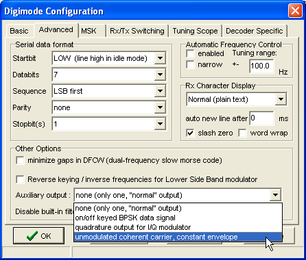
(screenshot of the 'digimode configuration' dialog, 'advanced' tab)
- AFC enabled
-
If this checkmark is set, the decoder will adjust the center frequency during
receive (if the supported in the used mode).
- AFC tuning range
-
Defines, how far (in Hz) the AFC'ed center frequency may 'walk away' from
the orginial RX center frequency.
- Narrow AFC
-
If this checkmark is set, the AFC reacts very slow and has a reduced tuning
range. Good for noisy signals (depending on the mode. For many modes, this
control has no effect at all !)
- Tuning scope
-
Defines the mode of the tuning scope, like "Bit phase vectors", "bit signal
over time", etc. In long-persistance-mode, you will see the usual
eye-pattern which is often used to check the proper function of the demodulator
and the bit synchronisation.
Note: Since the implementation of a "phase meter", there is a more flexible tuning aid outside the digimode terminal !
- Auxiliary Output
- The second output (usually 'R5', the soundcard's right audio channel)
can be used to produce an auxiliary output signal, which can be picked
from a list:
- On/Off keyed BPSK signal
-
This option has been implemented for users of 'switching mode' transmitters for PSK31
(and its slower variants). To use this, you must set your audio card to "Stereo
Mode" in Spectrum Lab's main configuration. If enabled, the LEFT audio channel
produces the usual amplitude-shaped PSK31 signal, while the RIGHT audio channel
produces the phase information (0 or 180 degrees) for a hardware phase inverter
in the transmitter. The signal is an on/off-keyed audio 'carrier' because
the audio card cannot produce DC signals. Use a rectifier diode and a small
capacitor to turn this into a digital control signal for your transmitter.
This only works for PSK31 & PSK08 with 'pulse shaping' enabled.
- Quadrature output for I/Q modulator
-
Special feature to produce single-sideband signals. For some (most?) digimodes,
the modulator can produce inphase- and quadrature outputs. This greatly
simplifies the transmitter hardware, because no narrow filter will be required
to remove the unwanted sideband. Some notes on I/Q signal processing with
Spectrum Lab can be found here
(including how to switch the spectrum analyser into I/Q-mode).
The quadrature output generated this way (using a soundcard with stereo output) can be used to drive a phasing 'exciter' like this one.
- Unmodulated coherent carrier, constant envelope
-
This output supplies the unmodulated carrier wave,
which may be required for phase-coherent modulation experiments (coherent CW,etc..).
For transmitters which divide the signal frequency by two (or even by four, to produce a highly symmetrically signal for a MOSFET bridge), set the TX center frequency accordingly.
The primary output (usually LEFT audio channel) will then provide the amplitude modulation, including pulse shaping, while the auxiliary output produces a really 'continuous' (coherent) wave which starts at the begin of a transmit cycle and ends when all data bits are through.
Note: So far, the 'unmodulated coherent carrier' output only works for a few modulation types, for example with ASK (amplitude shift keying), OOK (on-off keying), but not with FM (frequency modulation).
- Serial Data Format
- Once used to define the format of asynchronous data transmissions, namely the old teletypewriter stuff. Not very common these days, and almost useless for modern synchronous ("block-") transmissions.
See also: Basic Settings
7.3 RX / TX Switching Options
On this tabsheet in the terminal configuration window, the switching between RECEIVE ("RX") and TRANSMIT ("TX") can be customized. By the time of this writing (2004-10), the following options existed :
-
Switch to "receive" automatically if the TX-buffer is empty
This option is highly recommended for the "slow modes", especially if there is the risk that the radio operator falls asleep. -
Switch to "transmit" automatically if the TX-buffer is not empty
Only useful for certain slow modes if you can type faster than the terminal can send. Not recommended for fast modes, because this may result in unwanted gaps between the transmitted characters ! -
Half duplex operation, either ADC or DAC enabled, but not BOTH at the same
time
This option was introduced because some older soundcards caused problems when the analog/digital- and digital/analog-converters were running at the same time (causing dropouts in the outgoing audio stream, or unwanted "oscillation" from the internal feedback). -
While transmitting, connect spectrum analyser to the modulator output
Especially helpful in the HELL modes, to use the spectrogram display as monitor for your own transmission. When switching from "TX" to "RX", the spectrum analyzer will be connected to the audio input again ("L1" in the circuit ).
- See also:
- Digimode Settings, Advanced Settings
8. Interpreter Commands for the Digimode terminal
A few settings and parameters of the 'digimode terminal' can be controlled
from Spectrum Lab's command interpreter. To modify
a parameter, use a formal assignment like
"digimode.decoder.afc.freq=1200". The token "digimode" can be
abbreviated as "di" if necessary.
Functions and procedures to control the digimode terminal are:
- digimode.decoder.afc.freq
- Read or modify the current AFC frequency. A typical use is to connect one of Spectrum Lab's frequency markers to the center frequency of the digimode decoder (if the used mode supports a kind of automatic frequency control, like PSK31).
- digimode.rx.count
- Returns or clears a counter for all received characters. To clear the counter, set it to zero like this: digimode.decoder.rx.count=0 .
- digimode.rx.text
-
Retrieves or modifies or clears the text in the RX window as a single string
of characters. To erase the text in the terminal's RX window, assign an empty
string to it:
digimode.rx.text="". Note: The configuration "GB3SSS_beacon_monitor" uses this function to print the output of the PSK31 decoder into the spectrogram shortly after the end of the beacon's transmission cycle. - digimode.state
-
Accesses the current state" of the digimode. Possible states are: 0=terminal
"off" (passive), 1=receiving, 2=transmitting. By assigning a value, you can
change the state through the interpreter (this is possible for other applications
too, using the mini-web-server or the
message-based communication protocol). Example:
digimode.state=1 : REM receive - digimode.freq
- Read or modify the audio center frequency for transmission.
- digimode.mode
-
Get or set the operation mode. Possible values are:
0 = mode is unknown or not important for the current code set and/or modulation
1 = single characters
2 = blocks / packets of data bytes
3 = Hellschreiber or similar image-transmission modes (not really "digital") - digimode.modulation
-
Modulation type. Possible values (by the time of this writing..) :
0 = no modulation (emit "baseband" signal)
1 = other modulation types except the following... (possibly dictated by mode or other parameters)
2 = ASK (amplitude shift keying only; includes on/off keying)
3 = ASK+FSK (amplitude+frequency shift keying, combined)
4 = PSK (phase shift keying, but neither BPSK nor QPSK)
5 = FSK (frequency shift keying only)
6 = APK (amplitude+phase keying)
7 = PMT (parallel multi-tone, only used for certain HELL modes)
8 = BPSK (binary phase shift keying)
9 = QPSK (quarternary phase shift keying)
10 = OQPSK (offset-QPSK)
11 = MSK (minimum shift keying)
12 = m-valued PSK (not supported by the digimode terminal itself)
13 = MFSK (multi-frequency shift keying; only one "tone" at a time)
14 = CMT (chirped multi-tone, used for DF6NM's chirped HELL)
- digimode.codeset
-
Read or modify the number of the codeset. Possible values are:
0 = unknown (dictated by the DLL used to generate the code; or -without a DLL- sends 'raw ones and zeroes', one symbol per digit)
1 = Morse code
2 = Baudot (teletype)
3 = ASCII, 7 bit
4 = ASCII, 8 bit
5 = G3PLX Varicode (widely used in PSK31)
6 = WSQ 'Varicode 3'
7 = reserved for future use
8 = Random bitstream (for testing purposes)
11 = RTC SR104 (used by DGPS beacons on medium wave)
12 = DTMF ("telephone touch tones") - digimode.symrate
- Get or set the symbol rate ("speed"), measured in symbols per second like in the configuration screen.
- digimode.tx(<string to transmit>)
-
Clears the old contents of the TX buffer, switches to transmit, and sends
the specified message regardless of the text entered in the terminal. This
can be used for beacon-like transmission (use this command in a PERIODIC,
SCHEDULED, or even a CONDITIONAL action).
The text itself can be a simple constant string of characters, but also a variable expression like in the following example:
di.tx(str("hh:mm:ss",now)) : REM send some text with the digimode
    terminal
(there will possibly more here in future..)
Note: You can invoke interpreter commands from the transmit window itself, with an exclamation mark embedded in angle braces, as described here. But usually, interpreter commands will be invoked from the command interpreter window, or from the periodic/scheduled/conditional event window .
See also: Spectrum Lab's main index .
8.2 Calling interpreter commands from the terminal's transmit window
For some *very* special applications of the digimode terminal, it is possible
to invoke any interpreter command (not
only interpreter commands for the digimode
terminal ) from the transmit window. The commands must be embedded
in angle braces, and preceeded with an exclamation mark like in the following
examples.
Here is an example for text in the TX window, with an interpreter command which will be invoked when the transmit pointer reaches it:
The quick brown fox jumps over the lazy dog.
<!sp.print("Transmission finished")>
This example first sends a line of text, and then prints the message "Transmission finished" into the main spectrogram.
Notes embedding interpreter commands in the transmit text:
-
The command, including the embedding angle braces, must not be longer than
80 characters.
-
Such interpreter commands are not limited to commands
for the digimode terminal; in fact
any interpreter command may
be invoked this way. But do not call slow subroutines from here because it
may disturb the transmission.
-
The execution of the interpreter command is usually delayed until all characters
before the command have been transmitted. However, in some cases (especially
for high data rates) this may not work properly - for example, if the digimode
driver uses an internal buffers of unknown size. In such rare cases, use a delay
command in the sequence to make sure the terminal has finished transmitting
'important' data bits before you modify settings which affect the ongoing
transmission.
9. Appendix
Sending VARICODE via MSK
Varicode is a codeset with variable length ("bits per character"), optimized for plain english text. Characters are separated by two consecutive "zero"-bits, which do not occurr in any of the VARICODE characters. Please read the excellent PSK31 documentation by Peter Martinez (G3PLX) if you are interested in the details. The original PSK31 mode uses BPSK or QPSK to transmit the varicode characters. Here, for MSK (minimum shift keying), the following bit encoding scheme is used:
- A "zero"-bit is signalled by a transition in the TX-frequency
- A "one"-bit is signalled by NO transition in the TX-frequency
That's all ! If no characters are in the transmit buffer, a sequence of logic "zeros" is transmitted, which produces a wharbling "idle tone" of alternating high/low frequencies. This corresponds with the 180°-phase reversals in BPSK31. Without this, there would be no bit synchronisation for the receiver if the transmitter has "no characters to send". This happens regularly in the keyboard-to-keyboard communications, which PSK31 (and now MSK31) was intended for. If signals are too weak for MSK31, use MSK08 instead.
You can easily tell an MSK31 signal from a PSK31 signal by looking at their spectra in the waterfall display:
- The PSK31 "idle tone" consists of two lines, exactly 31.25 Hz apart, equal amplitudes
- The MSK31"idle tone" consists of three lines, the outer two spaced 31.25 Hz, the line in the center is about 10dB stronger than the two outer lines.
Of course, the spectral spacing of the idle tones will be different for lower symbol rates.
Last modified : 2020-10-23
Benötigen Sie eine deutsche Übersetzung ? Vielleicht hilft dieser Übersetzer - auch wenn das Resultat z.T. recht "drollig" ausfällt !
Avez-vous besoin d'une traduction en français ? Peut-être que ce traducteur vous aidera !