Image rejecting direct conversion
receivers
(Quadrature signal processing with Spectrum Lab)
Last modified in July 2019
Contents
See also: SpecLab's main index,
a Phasing exciter for digital modes on LF (quadrature modulator, also usable for MF).
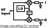
In it's basic form, a direct conversion receiver (without image-rejection) multiplies the received signal (frequency f_in) with an oscillator tuned closely to the desired frequency (oscillator frequency f_osc). The problem is, the same audio frequency is produced if f_in is slightly above, or slightly below the oscillator signal. For example, with f_osc=10.000 MHz, signals at f_in1 = 9.999 MHz and f_in2 = 10.001 MHz will both produce a difference frequeny of 1 kHz. To cancel the unwanted image (for an image-cancelling "single-sideband" receiver), two mixers are used instead of one, and a local oscillator (LO) with quadrature output (90° phase shift between the outputs, like cosine and sine). Here is one of a few dozen principles of such a receiver:
The downconverted (low-frequency) output signals from both mixers are then passed through two equal, relatively simple lowpass filters. These outputs are called the "inphase" (I) and "quadrature" (Q) component (*). From the phase relation between "I" and "Q", the following processing stages can determine if a signal is "above" or "below" the LO frequency (with this complex signal, negative frequencies are possible which we will see later when looking at the spectrum). In a classic DC-receiver with demodulator, a 90° audio phase shifter is required to combine I and Q into an audio signal. More explanations and examples for complete image-cancelling DC receivers (including the audio phase-shift circuit) can be found in the ARRL handbook. Other input stages, like the input part of the Tayloe Detector work too (just google for it, leave the polyphase network away).
Here, we don't need an audio phase shifter because the I/Q-signal goes straight into the soundcard for any further processing. This principle is sometimes called "software defined radio" though it still requires an analog frontend. Popular examples (in the radio amateur community) are SM5BSZ's Linrad project, the Softrock transceiver series, and many others.
The following chapters will explain how to configure Spectrum Lab for I- and Q-output. In this document, the term "DC receiver" means "any direct conversion receiver with I- and Q-output".
First adjust the soundcard's input volume properly: Avoid overdriving the inputs, but don't let the input signals too weak. Use a low-noise amplifier if required, instead of cranking up the soundcard's input gain because the amplifiers in standard soundcards are often worse than what you can achieve with a moderately priced operational amplifier. (The SM5BSZ site shows how this can be put to-the-max for VHF downconverters, fortunately LF/MF/HF-receivers can be made simpler because you can add a simple preselector before the mixers).
To get the DC receiver running, the soundcard must be switched to "stereo" mode, the FFT input type set to "Complex, separate I/Q inputs", and these two I/Q inputs connected to the left and right input channel of the soundcard. This could be done on SpecLab's circuit window, but it's easier to start with one of the preconfigured settings :
In the main menu, select "Quick Setting" .. "Image-cancelling DC receiver"
.. "Broadband display, 48 kHz sampling rate" .
(if you are sure your soundcard really supports 96 kHz sampling rate, you
can select 96 kHz too for a really broad display)
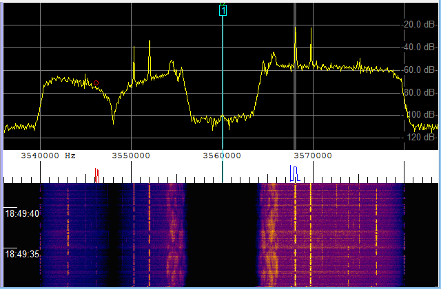
Because of the "negative" and "positive" frequencies covered by the analytic (complex) signal fed into the spectrum analyser, the frequency scale now covers -24 kHz to +24 kHz (for the 48 kHz sampling rate), or even +/- 48 kHz for the 96 kHz sampling rate. In the latter case, the spectrum will look like this (with a DC receiver connected of course):
(Spectrogram covering +/- 48 kHz with 96 kHz sampling rate and I/Q-input,
note the strong signal at +35 kHz and the unwanted image at -35 kHz)
Because there will always be slight imbalances and unwanted phase shifts in the analog circuitry of the DC receiver, the rejection of the unwanted sideband (at -35 kHz in the above screenshot) may be improved by carefully adjusting the gain balance and phase shift between I- and Q- input. This can be configured in the circuit window (click on the A/D-converter block on the left side), or in the Audio-IO tab of the main configuration dialog (click on the link "I/Q input adjustment"). Both ways will take you to the following context menu in the circuit screen:
(screenshot "I/Q input adjustment" in the circuit window)
If high and low frequencies seem to be reversed with your hardware, just exchange I and Q (doesn't matter if via hard- or software ... for the latter, reverse the analyser's input channels in the circuit window).
The I/Q input adjustment must be turned on by selecting the item "Enable amplitude- and phase adjusment for I/Q input". This allows you to quicky turn the adjustment on and off, to check if it "does any good" for the unwanted-sideband-suppression in the spectrum analyzer. Two parameters are required to adjust the DC-receiver for maximum sideband suppression:
"I/Q adjustment: gain balance correction" (in percent): compensates unequal gain between I- and Q-channel in the DC receiver
"I/Q adjustment: phase offset" (in degrees): compensates small phase errors between I- and Q-channel (the correction value is ideally zero, if the phase angle between I- and Q- channel is exactly 90°).
Clicking on any of these "adjustment" parameters opens a small input box where you can enter the value in numeric form. But you will usually not know what to enter, so set the checkmark "Connect To Slider" in the small input box, and click "OK" to close it. The parameter will then be connected to the large vertical slider on the right side of the circuit window, as shown in the screenshot above. The combo box below the slider shows what the slider is connected to (in the screenshot: "I/Q input balance correction"). Slowly move the slider up or down to maximize the rejection of the unwanted sideband in the spectrum display. Do the same with the "I/Q input phase correction" to minimize the unwanted sideband even further. Because both controls affect each other (to some extent), it may be required to repeat this process one or two times. It may be possible to get a rejection of the unwanted sideband of up to 80dB (or more, if your DC receiver is better than the author's).
Note:
Do not swap left and right channel through the ADC context menu after adjusting the I/Q parameters. For some strange reason, the sideband-suppression got worse after setting the option "Swap left and right input channel". By theory, upper and lower sideband (USB+LSB) can be exchanged this way.
< To Be Continued >
Not only the spectrum analyser, but also the FFT-based filter can optionally process (modulate, demodulate, filter..) quadrature signals. Details about possibilities and configuration of the FFT filter is in another document.
With the FFT-based filter in "I/Q-mode", you can...
A sample configuration to generate an I/Q stream with the FFT-based audio filter is described here .
Disappoing result when trying to process the "IF"-output from an IC-7300
as an I/Q signal (as any decent SDR would allow). This already shows the
maximum obtainable bandwidth, about 15 kHz with the radio switched to "FM" !
< To Be Continued >