Interfacing to the Receiver AADE DFD2 w/TXCO Instructions
Printed Circuit Board Assembly ||
Testing || Wiring the LED back-lit display
Step Two
Preparing the Cables || Setting the VFO Frequencies
Setting the 455 kHz Offset || Automatic Switching Setup
Connecting the Frequency Counter to the Receiver
Mounting the Counter on the Receiver
Checking the Readouts for the BandsCircuit Information
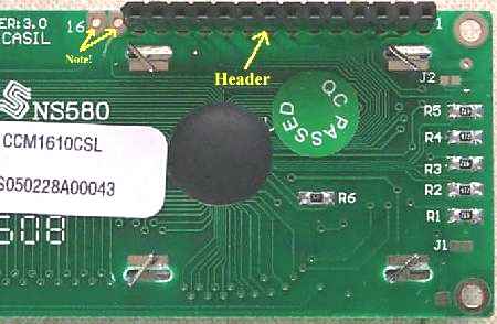
 Please see this Picture for an illustration of some soldering tips. Use the smallest soldering tip you have. The soldering pads are small and a large tip will cause trouble. Be very careful with a large tip and check for solder bridges to ground. For detail information on the theory and design of the frequency counter, check out Neil's article "A PIC-Based Digital Frequency Display", May 1997, QST, pp 36-38. Topics covered are Theory of Operation, Setting up the DFD, and Operating Tips. For more detailed information on these counters, check out Neil's web site: http://www.aade.com |
|
The instructions for the DFD2 that uses a 10 MHz or 16 MHz crystal for the oscillator are located at DFD2 10 & 16 MHz Instructions. After building the unit return here and start at Testing If you are using the DFD2 with the 16 MHz crystal, please click here for new information on adjusting the crystal frequency.If you have the 20 MHz TXCO module, which is currently being shipped with the kits, follow the instructions below. |
|
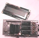
There a 3 general steps to complete assembly and packaging of the DFD2. 1. Choose the final installation method. The suggested location is on the bottom blank PCB board. If you are building a case for the receiver, it is suggested to move the counter at least 3" from the receiver boards to help prevent counter birdies getting into the receiver. The optional back lighted display is included with the kits that are purchased with the receiver. 2. Assembly of the printed circuit board (PCB) and display module. 3. Final testing and radio interfacing of the completed unit. There is an optional aluminum enclosure available from AADE that includes a plastic bezel. The DFD2 has inputs for 3 signals. The connections are soldered directly to the pads on the counter PCB with 50 ohm miniature coax. The BFO connection is not used with the receiver. You may also wish to have an on/off switch. An on/off switch is recommended to eliminate the birdies the display generates for critical receiving conditions. A switch is not supplied with the kit. |
|
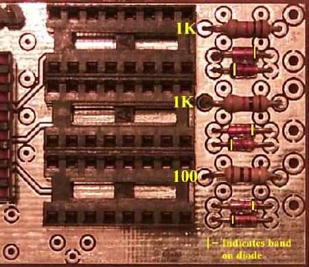
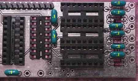
Begin the actual PCB assembly by sorting out the supplied components. A Parts List is included with the kits shipped with the receiver, including additional parts for automatic switching of the bands. Assemble the PCB per the following illustrations: |
|
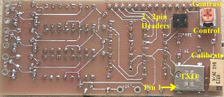
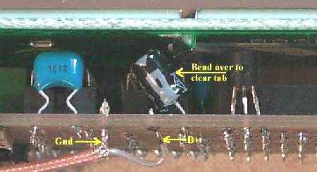
____Carefully inspect all of your solder connections, the polarity of the diodes, voltage regulator, the electrolytic capacitor, and the notch of the IC�s. ____Adjust the contrast control fully counter-clockwise. ____Plug the display module into the PCB 14 pin header. ____Attach the power supply, 8 to 12VDC, or 9V battery leads, to the marked pads on the back of the board near the bottom. Be sure to observe polarity with the negative lead to the grounded pad. (Picture) If you reverse the power connections, the 78L05 will smoke. Not to worry, after replacing the 78L05, the counter should work. ____You should see some frequency displayed. Adjust the contrast control for the desired effect. |
Wiring the LED back-lit displayThe back-lit module has a block of LEDs behind the LCD display. It is powered from pins 15 and 16 with pin 15 being plus and pin 16 being minus (usually ground). The voltage drop across the LEDs is 4VDC. The current can range from 20ma to 150ma. The dropping resistor required is R = (V-4)/I where I is the desired current and V is the supply voltage. One method that works well is to power it from the 78L05 regulator on the DFD2 as follows: ____On top of the display module, solder an insulated jumper wire from pin 1 (ground) to pin 16 (or the top connection of the LED module on the right side). ____Solder a 33ohm 1/4 watt resistor from pin 2 (+5VDC) to pin 15 (or the bottom connection to the LED module on the right side). The display is about as bright as a car radio dial at night. |
Preparing the cables and soldering to the Frequency Counter PCB____Measure and cut two 16" pieces of 50 ohm Teflon cable. 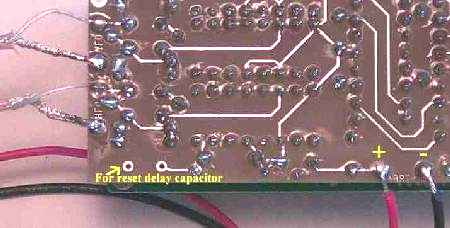 ____Solder the cable prepared for the Crystal Oscillator to the HFO input (bottom set of pads). ____The BFO input will not be used with the receiver. Do not install the 74HC4046 in the top socket. Or use a small piece of bare wire and short the BFO input to ground (directly on the PCB) and solder the jumper (Not necessary if the chip is not installed). Setting the VFO FrequenciesIf you do not have a bench Frequency Counter and need to use the DFD2 to set the VFO frequencies, follow these instructions. If you are using a bench counter to set the VFO, jump to Setting the 455 kHz Offset ____Remove all the 74HC4046s from the counter PCB. ____Apply power to the frequency counter and set the coarse (top pot) and fine (bottom pot) adjustments to show zero frequency on the display. Turn the pots counter-clockwise to set to zero. Sometimes the counter will show all squares and no digits. Disconnect and re-apply power and the digits should show. Also, turn the viewing angle of the display to make sure they are visible. ____Disconnect power to the display.____Install a 74HC4046 in the middle socket. This will allow VFO energy to reach the counter. (Or remove the short on the VFO cable, leave the HFO cable shorted.) ____Attach the VFO cable from the frequency counter PCB (center pair of pads) to the "Freq Cntr" box at the output of the VFO oscillator. ____Turn on the power to the receiver and the Frequency Counter. Be very careful of reverse polarity connections. A reverse polarity connection to the frequency counter will blow the voltage regulator (78LO5). Use a diode at the 12 Volt input to the Frequency Counter if you think you might make a mistake. Band side of the diode goes toward the board. ____The Frequency Counter will display the VFO frequency.____Set the 2/8 ceramic trim pot (labeled 14.068) to its middle position. Line up the slot in the adjustment screw with the capacitor pins, with the rotor plate on the end with the arrow. The rotor plate is the part of the top with the metallic color. ____Spread or compress the VFO toroid coil to set the frequency as close to 14.068 as possible. Note: All tuning to make the frequency reach 14.068 is done by modifying the turns on the toroid. If the frequency is too low with the turns moderately spread apart (13 MHz to 13.5 MHz), remove one turn on the toroid. If the frequency is too high, add a turn to the toroid. (This may require rewinding the toroid for a clean appearance, but having the frequency read too high, >15MHz, is unlikely.) ____Secure the VFO toroid by whatever means you have decided. Some options are a small plastic wrap, a 4-40 screw/nut and 3/16" rubber grommet (cut to fit into the center of the toroid), or pour wax from a candle (let wax cool before proceeding). Picture____Re-adjust the 2/8 ceramic trim pot labeled "14.068" to 14.066 MHz (Gives some room at the low end of the band.) ____Set the receiver to 40 Meters. Bandpass switch to the 40/30 side and the Crystal Filter switch to the 40/20 side. One LED should be on next to the 10.545 relay. ____Adjust the yellow trimmer next to the 10.545 relay for a frequency between 10.540 MHz to 10.543 MHz. (Gives some room at the low end of the band.) ____Set the receiver to 20 Meters. Bandpass switch to the 20/17 side and the Crystal Filter switch to the 40/20 side. Two LEDs should be on. ____Adjust the yellow trimmer next to the 10.445 relay for a frequency between 10.440 MHz to 10.443 MHz. (Gives some room at the low end of the band.) Setting the 455 kHz Offset on the Counter____Remove the VFO input 74HC4046 IC (middle chip). All the 74HC4046 chips should be removed for this adjustment. ____Make sure the reading is 0 kHz. This is done by turning the trimpots all the way counter-clockwise. 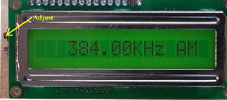 ____Turn the coarse pot (upper one) clockwise to 384 kHz. 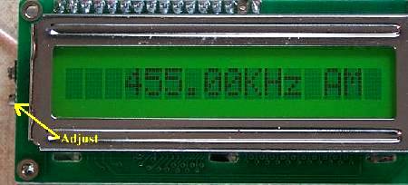 Automatic SwitchingThe offsets and the adding/subtracting are done at Pins 12 and 13 of the PIC16C71. Pins 12 and 13 are brought out to a four pin set on the back of the counter. The chip has 100K internal resistors that bias the pins to 5 volts. Two of the pins are grounds and the offsets are normally set by using a jumper to ground the necessary pins. With this receiver, wires are soldered to the left side pins (looking at the back). The right side pins are grounds. The left side pins are labeled "upper jumper" and "lower jumper" in these instructions. There are two ways to connect the Frequency Counter to the receiver to achieve automatic switching of the bands on the counter. One is by using a small interface unit that uses diodes and two NPN transistors that connect to the switches on Board 1 of the receiver. The second one is by using a rotary switch. The easiest one to wire is a two section rotary, either one wafer with two sections or two wafers. A rotary switch with one wafer can be used but is a little more complex to wire. The "AADE DFD2 Auto Switching" page shows all the options available. Choose one at this time and wire it to the counter. Connecting the Frequency Counter to the Receiver____Attach the VFO cable from the Frequency Counter (middle pair of pads) to the VFO oscillator output box labeled "Freq Cntr". PictureNote: The "Frequency Counter" output between the VFO amplifiers will not be used to drive the Frequency Counter. This connection overdrives the Frequency Counter and causes birdies in the receiver. ____Attach the HFO cable from the Frequency Counter (bottom pair of pads) to the Crystal Oscillator output box labeled "Freq Cntr". Picture____Install the middle and bottom 74HC4046s. Leave the top one empty. The top one is the BFO input and will not be used. 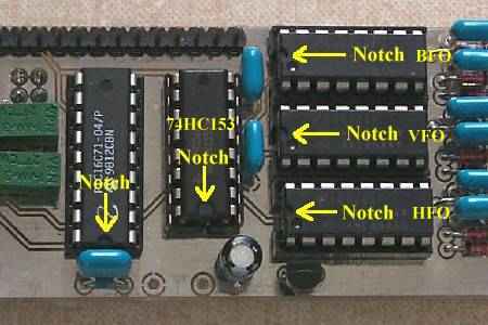 |
|
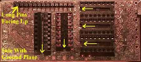
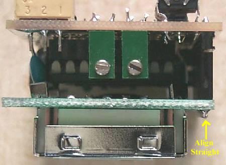
Getting the birdies of the counter out of the receiver has been researched for many hours. Just recently an accidental discovery showed the best way to mount the frequency counter for minimum birdies into the receiver. Almost all the noise from the counter comes from the LCD updating circuit and is radiated by the display bezel and the display itself. Normally one would think that using good grounding techniques would eliminate that noise. However, when adjusting the counter frequencies one day, the display was insulated from ground and there was no display noise in the receiver! A ground loop with the display must make the noise float in the ground circuit of the receiver. Therefore, when mounting the frequency counter, DO NOT ground the display, let it float! The only ground to the display should be at the back of the PIC PCB ground connection on the back of the counter. Since the mounting holes for the frequency counter are in the display board, this presents some extra effort to mount the display without grounding it. Tito Magluyan, AC5QC presented the following idea on mounting the frequency counter. Using the teflon screws was added on later. Using teflon screws and nuts are the easiest way to insulate the display. Tito used 12-2-G house wiring to make the mounting hardware. Turns out #12 solid copper wire scrapped from house wiring fits very nicely inside the mounting holes of the display. Cut a couple of small pieces, bend one end around to make a place to mount a screw, then bend the other end to go through the bottom mounting hole of the display. Take a teflon screw and run it through the bottom of the board and secure with a nut. Mount the display with the #12 copper wire mounting holes, and then take a second nut to secure the display. The picture below shows how it is done a lot easier than trying to explain the process: 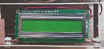 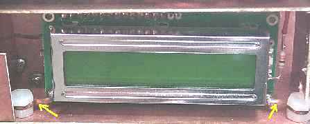 Yellow arrows point to the #12 house wiring that is used to help mount the display. The #12 solid copper wire just fits inside the mounting holes of the display and are soldered to the display PCB. In case teflon hardware is not available, a trip to the hardware store yielded some 1/8" nylon wire clamps found in the wiring section. 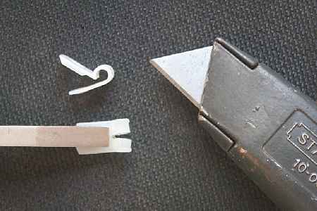 A slot is cut in the middle of the nylon clamp for the PCB board to slip into. Cutting the middle of the nylon clamp with a razor blade can be dangerous as the nylon is very hard. I used a hack saw blade to make an initial cut in the middle of the clamp, then a razor blade was used to make the slot wide enough for the PCB board. A pair of pliers (or a pair of vice grips, or a small vice) is used to hold the nylon clamp. 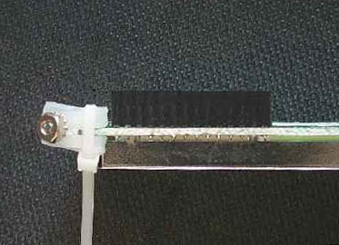 Then a tie wrap (the smallest available, approximately 1/8" or smaller) is use to mount the nylon clamp to the display mounting holes. 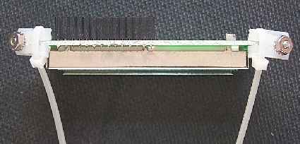 Picture shows both sides with the modified nylon clamps. Hardware (4-40 screw and nut) is used to hole the clamp together for easier handling. 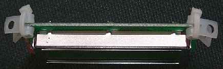 Picture shows the final product with the wire wraps cut. 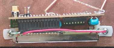 Final mounting of the display. A small shield should be put around the counter to eliminate the remaining noise. One that just covers the counter between the top of the display and the bottom board of the receiver pretty much leaves a clean receiver. Single sided blank PCB shield material is added to the kit for this purpose. Tin snips prove to be the best way to cut this material. You can also scribe a line on both sides with a sharp razor blade or knife and break apart the pieces you need. |
|
If the readouts are not correct for the bands, remember that the VFO frequencies have already been set correctly and the problem has to be in the Automatic Switching circuit. Check the jumper connections on the PCB - make sure the wires are not soldered to the ground side. If readouts are still not correct for the bands, go to DFD2 Diagnosis Thirty Meters____Set the Crystal Filter switch to the 30/17 position. Jumper Settings: Seventeen Meters____Set the Crystal Filter switch to the 30/17 position. Jumper Settings:
18.068 (17 Meters) Forty MetersNote: Forty Meters must be set before Twenty Meters. ____Set the Crystal Filter Switch to the 40/20 position. ____Jumper Settings: Twenty Meters____Set the Crystal Filter Switch to the 40/20 position. Jumper Settings:
14.0 MHz (20 Meters) General Information on the Action of the JumpersThe zero ohm jumpers on the four post header determine the +/- of each frequency input. Top Jumper off is plus for RF = HFO + VFO +/- BFO(IF), Bottom jumper off is plus for RF = HFO +/- VFO + BFO (IF), |
|
|
Note: Isolating the display from ground has solved the problem of birdies getting into the receiver. The following method was suggested before the discovery of floating the display from ground. The following information is left here in case someone might need to use these techniques in a build where they must be used to eliminate the noise from the counter. The elimination of birdies from the AADE Frequency Counters, or from any counter, needs to be approached from several different angles. Filtering the power supply, shielding the counter, and having a good ground attached to the receiver all need to be considered. The frequency counters supplied with the kit will have a 20 MHz TXO to raise the running frequency of the counter out of the range of the receiver. Most of the birdies of the receiver have been found to come from the updating of the LCD display. Sometimes a 10 MHz signal from the 20 MHz TXO will be heard, divided by the counter. If the kit is built in a case, moving the frequency counter 3 to 6 inches away from the receiver boards will help immensely in keeping birdies from getting into the receiver. Filter the power supplyThe best way to isolate the power supply line to the counter is by the use of a three terminal regulator (78xx series of regulators). Use a 7808 or 7809 just inside the shielding for the counter. Place a .01 bypass ceramic, plus a 100 mfd (or any high value electrolytic) at the input terminal of the regulator. Solder a 2.2 mfd tantalum or electrolytic at the output terminal of the regulator. Do not place a .01 at the output of the regulator, as this may cause oscillations at the regulator. Higher value electrolytics at the output may be used, but the optimal value is 2.2 mfd. ShieldingA good shield is absolutely necessary. When the counter is placed right below the First Mixer, as shown in the prototype pictures on this web site, no shielding yields birdies that nail the S-Meter. A top cover placed directly between the counter and the First Mixer lower the birdies to where there are no S-Meter readings. Picture Distance from the receiver also helps. When the receiver boards are placed in a box, with the counter placed 3" to 6" away on the front panel, the birdies are much easier to eliminate. Proper Drive LevelsDriving the frequency counter inputs too strong is a major reason for birdies getting into the receiver. Using a 3.3pf capacitor right at the outputs of the VFO (Picture) and the Crystal Oscillator (Picture), before any amplification, yielded a drive level that ran the counter and kept birdies at a minimum. A peak to peak reading on an oscilloscope was about .6 volt from both locations. Coupling capacitors of 3.3pf are used at the "Freq Cntr" connections at both the VFO and Crystal Oscillator. Grounding the Cables, the PCB board, and both sides of the PCB Shield BoxTwo coax cables are used to bring in the signals from the VFO and the Crystal Oscillator. To prevent ground loops which can carry birdies to the receiver, the insulation around the shields of the cables are removed and the shields are grounded on the inside of the case right where they exit. Picture The PCB board of the Frequency Counter should have a direct lead to ground. Picture Earlier models of the DFD2 did not have a ground connected to the bezel around the LCD display. Check with a DVM and see if yours is grounded to the PCB ground. The current batch that AADE is shipping are all grounded to the PCB board, but some earlier ones were not. If your bezel is not grounded, use a small file and file off the chrome on one side where it is least likely to be seen. Then solder a wire from the bezel to the closest ground. Be sure all the PCB material used to make the box is grounded. The best way to make sure is to solder loops across the PCB material on all the side panels. Picture Use RF Chokes at 12 Volt input, Switch pins, and Control wiresAn RF choke was placed where 12 Volts entered the box going to the 9 volt regulator. A feedthrough capacitor was also used, but may not be necessary. If feedthrough caps are not used, use shielded cable and solder the shield where it enters the box. RF chokes were used at the DFD2 + and - frequency control pins. The LCD updating noise was found at these pins and the RF chokes eliminates the noise. A Good GroundA good earth ground is needed for any of the suppression techniques to work, especially the power supply and the shielding. A "floating" receiver, one with no ground, cannot effectively utilize the bypass elements used in the receiver, not only for counter birdie elimination, but from signals traveling from the first board to the second. The receiver has been supplied with a lot of bypass caps and RF chokes to eliminate almost all the problems associated with signals going where they are not supposed to go, but without a good ground, the suppression is not as effective. Final NoteThe high impedance levels of this receiver, and the high gain of the VFO amplifiers make the problem worse with this receiver than with many other receivers using lower impedance levels and less gain in the VFO circuitry. In most cases, band noise helps cover up a lot of the residual birdies in the receiver. The birdies are not amplified the same amount as band signals. When a band is wide open, or an outdoor resonant antenna is used, there is little problem with the counter birdies. The most effective solution is to add an on-off switch to the counter, so when absolute freedom from interference is wanted, the counter can simply be shut off, and then turned on momentarily to check your operating frequency. |
Send E-Mail || Amateur Radio Receivers || Electroluminescent Receiver