
|
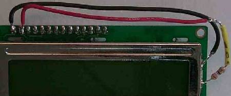
I didn't have a 33 ohm resistor handy, so a 39 ohm resistor is shown connected to the B+ input of the LED bank. (For those that notice such things) Red wire is B+ lead. The display above did not have pin 15 and 16. They would be to the right of the soldered connections at the top. 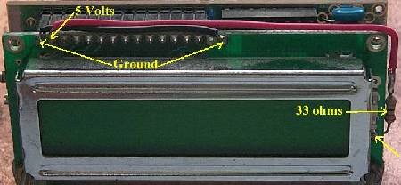 This display does have pin 15 and 16 and this is a suggested way to hook up power to the LED backlight. |
|
|
|
|
Send E-Mail || Amateur Radio Receivers || Electroluminescent Receiver || Back to DFD2 Instructions