
|
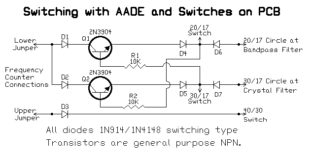
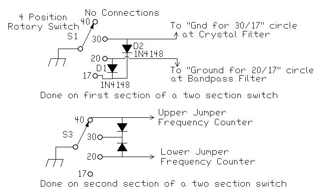
Presented here are several ways to incorporate automatic switching with the AADE DFD2. The first one, Switching the DFD2 with the Switches on the PCB, interfaces with the band switches on Board 1. Parts for this method are included in the Frequency Counter kit. There are several ways to hook up rotary switching for the receiver and for both the receiver and the AADE DFD2. The easiest one is to use a 2 pole rotary with at least 4 positions, check out AADE DFD2 and Receiver Switching with 2 Sections. No rotary switches are included with the kit. The first rotary schematic is for receiver switching only. The second schematic switches the receiver and the DFD2 with a two section rotary switch. The third schematic uses a one section rotary switch but is a little more complicated to wire. For those using the SWL version of the receiver, a three section rotary switch is used for switching the bands. Manual switching of the bands is shown in the SWL instructions. |
|
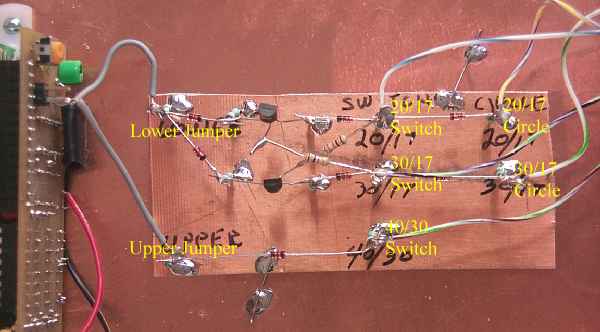
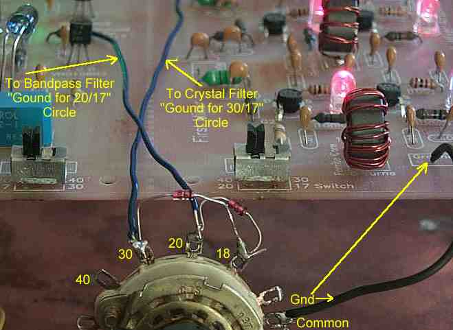
The picture above shows the switching circuit "ground plane" style soldered to the frequency counter and Board 1.. |
|
Parts needed: Watch out for the correct connections from the Bandpass and Crystal Filter connections. See below. |
|
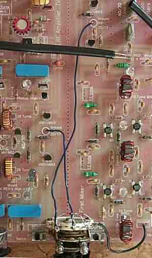
A wider view of how it all is connected. The switches on the board can be removed if the rotary switch is used. |
|
The rotary switch has been mounted on Board 1 with two standoffs. The space between the standoffs just accepts a standard size rotary switch. Notice the wiring to the switch and the connections on the board. Another place to mount the rotary is on a piece of PCB board soldered to the bottom plate. |
|
The receiver has its own rotary section and the frequency counter has its own rotary section. Some rotary switches have two sections on one wafer. These might be cheaper than a rotary with two wafers. Also, almost all now have more than four poles, i.e. 11, and are sold as universal rotary switches. They will work fine, just use four poles. Remember to use an RF Choke and .01 bypass capacitor at the jumper connections of the Frequency Counter when hooking up the counter section. See picture.
|
|
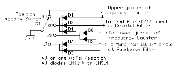
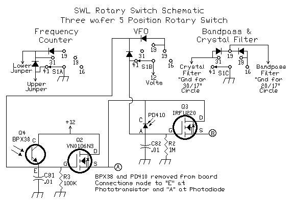
Thanks go to James Wallace of Rowlett, TX, who figured out the final schematic to make this circuit work and for his design of the schematic. James is an Electroluminescent Kit owner. Both switching circuits are combined on one section. The truth table for the Board Switches and Frequency Counter is the following: |
|
||||||||||||||||||||||||||||||||||||||
|
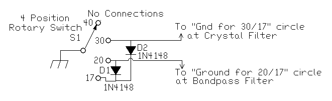
Diodes D2 and D5 isolate the counter switching and the receiver switching from each other. When D2 was not installed the 30/17 LED would not turn completely off and the Crystal Oscillator would not switch properly. Diodes D1 and D6 keep 12 volts from Board 1 getting into the Frequency Counter PIC. D1 also turns on the Upper Jumper for 30 meter operation. It is very important that these diodes (D1 and D6) are installed correctly! Or you will blow the frequency counter! D1 and D4 perform the function of the truth table for the Frequency Counter. D3 and D7 ground both the 30/17 and 20/17 switches for 17 meter operation. D4 and D1 ground both Upper and Lower Jumpers for correct readout on 30 meters for the Frequency Counter. |
|
Be sure to install the RF Chokes and .01 bypass capacitors on the jumper pins. See picture. They will help keep noise from the counter getting into the receiver. |
|
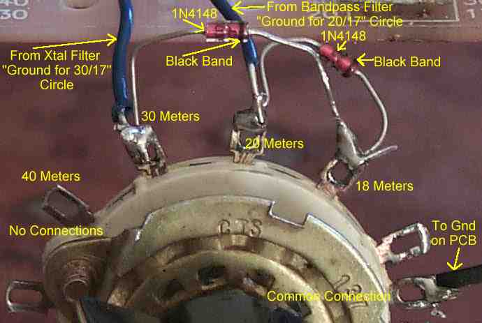
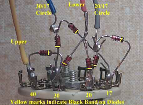
Picture shows the circuit installed on a single wafer rotary switch. Pay close attention to the orientation of the black bands on the diodes. |
|
All diodes are 1N914 or 1N4148 or similar. If you can't find a 5 position rotary switch, one with more positions may be used, just use the first five positions. There are some 11-12 position universal rotary switches that are easy to find and inexpensive in price at surplus part businesses. Notice that a ground connection goes to the common connection on the first and third wafers (counter and filters). A B+ connection goes to the common connection on the middle wafer (VFO). Be very carefull of the Frequency Counter connections, putting B+ on the jumper pins can blow the PIC. Frequency Counter Connections Looking at the back of the counter PCB board, the connections are made to the left pins of the jumpers (upper and lower). The right pins should show a connection to ground. Tin the pins first, then tack solder the wires to the pins being careful to get them on straight. Phototransistor Connection on Board 1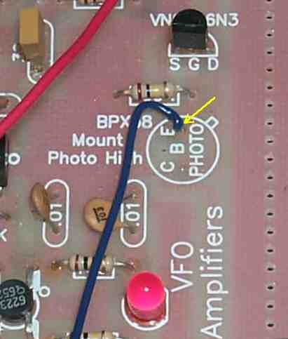 Photodiode Connection on Board 1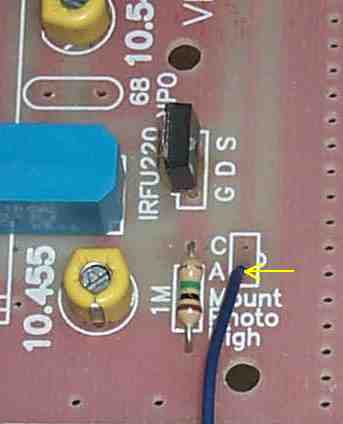 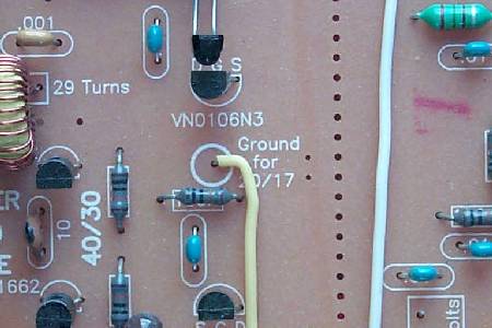 Picture shows the connection to the "Ground for 20/17" connection. This connection is at the Bandpass Filters. The wire is soldered to the bottom of the board if the rotary switch is mounted underneath Board 1. 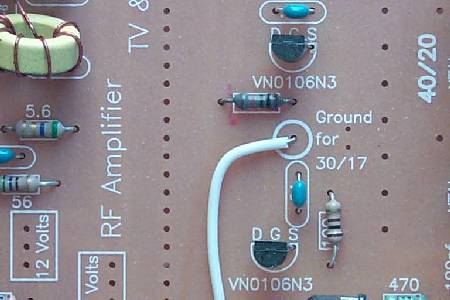 Picture shows the connection to the "Ground for 30/17" connection. This connection is at the Crystal Filters. The wire is soldered to the bottom of the board if the rotary switch is mounted underneath Board 1. |
Send E-Mail || Amateur Radio Receivers || Electroluminescent Receiver || Back to DFD2 Instructions