AADE DFD2
10 & 16 MHz
Instructions

AADE DFD2 Diagnosis

The following are instructions for the DFD2 that uses a 10 MHz or 16 MHz crystal.

This DFD2 was shipped before June 2005. New kits are being shipped with the 20 MHz TXO.


Please Note!: If you are using the DFD2 with the 16 MHz crystal, it can interfere with the 30 and 17 meter bands. The PIC divides the 16 MHz frequency by 4 which can radiate a 4 MHz signal into the 4 MHz crystal filter causing a constant tone in the output of the receiver that cannot be tuned.

Arrow points to crystal trim cap on the back of the PIC PCB.

The fix is to run the counter while listening to the 30 meter band and adjust the crystal trimmer capacitor on the frequency counter for zero beat in the receiver.

The signal level from the counter at zero beat is low enough that it does not interfere with reception of the 30 or 17 meter band.

Before Beginning Construction

There a 3 general steps to complete assembly and packaging of the DFD2.

1. Choose the final installation method. For example: standalone case or inside an existing rig; battery or DC supply power; and edge lighting or use of optional back lighted display.

2. Assembly of the printed circuit board (PCB) and display module.

3. Final radio interfacing and testing of the completed unit.

The final installation is limited only by your imagination and the physical space available to you. The optional aluminum enclosure available from AADE includes a plastic bezel. Model 2 of the DFD has inputs for 3 signals, which are typically RCA or BNC type chassis mount connectors. You may also wish to have an on/off switch, power selection (AC or battery), or other optional controls. You may also need to provide lights for display edge lighting or power to the optional back-lit display module. Knowing these things before you begin PCB assembly will allow you to install the correct wires and cables (coax) during board assembly.

Printed Circuit Board Assembly

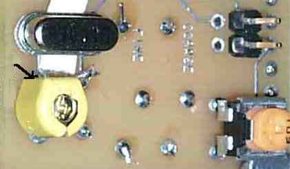
Begin the actual PCB assembly by sorting out the supplied components.

You should have the following parts:

a. Four 1K resistors (brown, black, red);
b. One 33 K resistor (orange, orange, orange);
c. One contrast control (3 contact potentiometer, 10K);
d. Nine .1 microfarad capacitors (marked 104, or 100.000 pfd which is .1 mfd);
e. One 22pfd capacitor (marked 22);
f. One 10 mfd capacitor (electrolytic polarized);
g. One crystal padding capacitor (2 contact variable capacitor, 3-30pfd) ;
h. Seven small signal silicon diodes (1N4148);
i. Five IC sockets (4 for 16 pin IC�s and 1 for the 18 pin CPU);
j. Two rows of 14 pins that mate to form the display adapter connector;
k. One 16mhz crystal;
l. One, 3 terminal voltage regulator (78L05);
m. One CPU IC (type PIC16C71 for U5);
n. One IC (type 74HC153 for U4);
o. Three IC�s (type 74HC4046 for U1, U2, U3);
p. One LCD display module;
q. One printed circuit board (PCB).
r. two 10K 15 turn trim-pots (general purpose DFD2 only)
s. four pin square post header
t. two zero ohm jumper to fit above header

Assemble the PCB per the following illustrations.

PCB shown component side. Black is copper (silver in reality)

Picture

1) Begin by installing the 7 glass diodes. Do not bend the leads next to the body of the diode or you can break the glass. The lead spacing is .4" Observe the polarity (bands) as shown above.

Picture

2) Install the four 1K resistors and the 33 K resistor

Picture

3) Install the five IC sockets

Picture

4) Install the nine .1ufd capacitors

Picture

5) Install the 10ufd electrolytic, the 78L05 and the 22pf capacitor If two 10K trimpots are included install them. These are not included if you have a microprocessor programmed for a particular radio.

6) Install the 14 pin male square post header

Picture

7) On the back (solder side) of the PCB, mount the contrast control (10K trimpot), The trimmer capacitor and the crystal. Make sure to space the crystal slightly off the PCB so that the metal can does not short any circuit traces. Be very careful soldering the crystal leads on the component side. It is very easy to bridge the solder to the ground plane. Check with ohmmeter to ground plane. Remove excess solder with solder wick. Install the four post male header as shown. Again be careful soldering on the top of the PCB to avoid solder bridges to the ground plane. Check the two pins opposite the contrast control to verify they are not shorted to ground. The two closest to the contrast control should be ground.

Picture

8) Plug in the IC's.

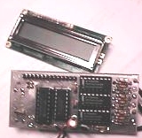
Solder the 14 pin female socket on pins 1 through 14 of the display module. Make sure it is at a 90 degree angle to the display module. (Picture)

After completion of these steps, go to Testing on the AADE's DFD2 Instructions page.

Send E-Mail || Amateur Radio Receivers || Electroluminescent Receiver


Last Update: 8/28/06
Web Author: David White, WN5Y Free Website Translator