|
I will NOT be held responsible for any
info that is listed here
ALL DONE AT YOUR OWN RISK ! |
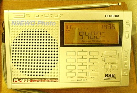
Tecsun PL-600 Audio Distortion Modification
Tecsun PL-600 Modification (You Tube Video)
N9EWO's Tecsun PL-600 Review can be found here (bottom of page).
Sangean ATS-803 / ATS-803A - Realistic DX-440
"Anti-Chuff" Modification
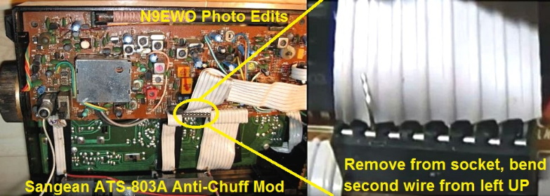
A very simple and fully reversible modification for the Sangean ATS-803 / ATS-803A (and many other variants)
that eliminates the "Chuff" sound when tuning. Ribbon cable easily unplugs and inserted back after
the above wire has been bent up. Has been verified to work as described by N9EWO. (N9EWO photo edits)
GRE "General Research of Electronics Inc."
Shortwave "HF" Receiver List.
"General Research of Electronics" (GRE) of Japan manufactured "Tabletop HF Communication Receiver" models.
Most were made in Japan (but not all). Sadly GRE is now a defunct company.
There may be more to this list (not saying it's complete) ?
With the help of "The Way Back Machine" (Internet Archives) a few interesting dated GRE history pages.
(our thanks to Paul L. WW2PT for the links)
GRE COMMUNICATIONS RECEIVERS (1978)
Introduction of the other companies product in the United States
GRE Company History
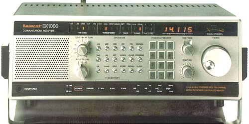
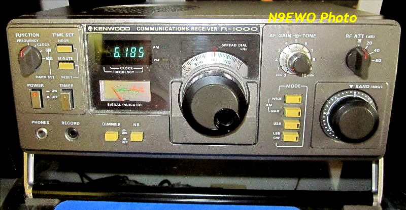
The "Made in Japan" Bearcat DX1000 Communications Receiver (not tested). After the sale of
"Electra" Bearcat to Uniden in 1984, Uniden continued to sell the DX-1000 for a few years after. YES....Uniden
actually selling a GRE manufactured product for awhile. It took a few
YEARS to sell out existing stock well past GRE
manufacturing it (which was only for about a year), as they were not a
"stellar" seller at around $ 500.
street price. Some samples will have a black sticker on the rear panel
indicating the ownership change of the company to Uniden. User reports
indicate that its nasty traits are very poor sensitivity with extremely
poor dynamic range. Uses similar bandwidth filters and types as with the Kenwood R-1000, including the nice 12 kHz bandwidth for wide audio quality when conditions warrant (model not tested) . See the "Ham Radio Today" March 1987 magazine review here (located on pages 28 to 32, PDF scan provided by World Radio History web site).
JRC NRD-525 Important Serial Number Information
HF RFI Generator - "Electronic Defrost Timer"
Early samples of the Tecsun PL-600
receiver suffered from extremely BAD audio distortion on LW / MW and SW
bands. This modification will clear the bug up (NOT TESTED by N9EWO).
With later production this nasty was apparently cleared up ? Be sure
and read this entire article right to the bottom of the page. "You
Tube" link shows the modification after the 1K (1000) ohm resistor was
added. NOTE : John's KB5AG modification indicates to use a 2K (2000) ohm resistor here ? Remember this is for the PL-600 and NOT for the PL-660/680 etc. !
Tecsun PL-600 Audio Modification (via "merseyradar" UK link)Tecsun PL-600 Modification (You Tube Video)
N9EWO's Tecsun PL-600 Review can be found here (bottom of page).
Sangean ATS-803 / ATS-803A - Realistic DX-440
"Anti-Chuff" Modification
A very simple and fully reversible modification for the Sangean ATS-803 / ATS-803A (and many other variants)
that eliminates the "Chuff" sound when tuning. Ribbon cable easily unplugs and inserted back after
the above wire has been bent up. Has been verified to work as described by N9EWO. (N9EWO photo edits)
Sangean ATS-803 / DX440 "Anti-Chuffing" Modification (via Rickw999)
The following mod will remove the "chuffing" heard while tuning the Sangean ATS-803 / Realistic DX440 radios. WARNING: Done at your own risk.
1. Place the radio face down on a suitable surface and orientate it so that the base of the radio is towards you.
2. Remove the battery cover and take out the D-cells. You do not need to remove the AA batteries but if you do will lose your clock and memories, so make a note of them before you go on.
3. Remove the six screws which hold the back of the radio in place. One of these is in the battery compartment.
4. Lift off the back cover and swing it over towards your left to lay it down. This is to avoid breaking off the wire going to the whip antenna.
5. Locate the 8-wire flat cable which runs from the circuit board above the loudspeaker on your right horizontally across to the rf/if board (see photo above). The cable plugs into an 8-pin socket which is located almost dead center in the radio on the RF / IF board.
6. Carefully remove the cable from its socket. Identify the second wire from your left in the cable. (Second to last on the side furtherest from the loudspeaker.) Bend this wire up and out of the way so that it will not plug back into the socket or make contact with the socket in any way.
7. Carefully plug the cable back into the socket and check that the wire you modified is not making contact with the socket.
8. Repeat steps 4 through 1 in reverse order and reprogram your clock and memories.
9. Turn on the radio and enjoy the lack of "chuffing". (Note : You may still hear a "thud" while tuning across a strong station.)
The main purpose of the muting circuit that gets disconnected by this modification is probably to make the set silent when you hit the"search" button. I personally think that it is a feature to hear the "search" in operation.
The only drawback in this mod is that it will allow all sounds to come thru. Even some that you might not want , such as turning on the power, switching between memories, ct. Its like a popping sound, even while band scanning. By attaching a 64K ohm resistor between the 2nd wire and it's socket, the popping is cushioned.
Other RadioShack / Sangean "Anti-Chuff" (muting disable) Modifications
- RadioShack DX-390 / Sangean ATS-818 (W9JES)
- Realistic/RadioShack DX-390 Shortwave Mute MOD The Right Way.
- RadioShack Realistic DX-375
- RadioShack DX-398 / Sangean ATS-909 (N1KGH)
- Radio Shack DX-440 / Sangean ATS-803/A Low Sensitivity Repair (N1NUG, You Tube Video)
See our PDF document here for detailed information and photos.
The following mod will remove the "chuffing" heard while tuning the Sangean ATS-803 / Realistic DX440 radios. WARNING: Done at your own risk.
1. Place the radio face down on a suitable surface and orientate it so that the base of the radio is towards you.
2. Remove the battery cover and take out the D-cells. You do not need to remove the AA batteries but if you do will lose your clock and memories, so make a note of them before you go on.
3. Remove the six screws which hold the back of the radio in place. One of these is in the battery compartment.
4. Lift off the back cover and swing it over towards your left to lay it down. This is to avoid breaking off the wire going to the whip antenna.
5. Locate the 8-wire flat cable which runs from the circuit board above the loudspeaker on your right horizontally across to the rf/if board (see photo above). The cable plugs into an 8-pin socket which is located almost dead center in the radio on the RF / IF board.
6. Carefully remove the cable from its socket. Identify the second wire from your left in the cable. (Second to last on the side furtherest from the loudspeaker.) Bend this wire up and out of the way so that it will not plug back into the socket or make contact with the socket in any way.
7. Carefully plug the cable back into the socket and check that the wire you modified is not making contact with the socket.
8. Repeat steps 4 through 1 in reverse order and reprogram your clock and memories.
9. Turn on the radio and enjoy the lack of "chuffing". (Note : You may still hear a "thud" while tuning across a strong station.)
The main purpose of the muting circuit that gets disconnected by this modification is probably to make the set silent when you hit the"search" button. I personally think that it is a feature to hear the "search" in operation.
The only drawback in this mod is that it will allow all sounds to come thru. Even some that you might not want , such as turning on the power, switching between memories, ct. Its like a popping sound, even while band scanning. By attaching a 64K ohm resistor between the 2nd wire and it's socket, the popping is cushioned.
Other RadioShack / Sangean "Anti-Chuff" (muting disable) Modifications
- RadioShack DX-390 / Sangean ATS-818 (W9JES)
- Realistic/RadioShack DX-390 Shortwave Mute MOD The Right Way.
- RadioShack Realistic DX-375
- RadioShack DX-398 / Sangean ATS-909 (N1KGH)
- Radio Shack DX-440 / Sangean ATS-803/A Low Sensitivity Repair (N1NUG, You Tube Video)
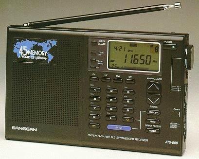
Sangean ATS-808 / Realistic DX-380 / Siemens RK661
"Anti-Chuff" Modification
"Anti-Chuff" Modification
Sangean ATS-808 / Realistic DX-380 / Siemens RK661 "Anti-Chuff" Modification (as N9EWO tested).
This involves removing 2 tiny surface mounted resistors. Please see our PDF document (click here).
This requires removing TINY 2 SURFACE MOUNT
resistors from the main board (R109 and R110, both 12K value). No need
to remove the main board as the resistors are located on the backside
on the right side of the main board near the bottom (as viewed with
rear cover removed). This modification will allow microprocessor noises
/ band changes etc…to irk through. But is much improved than having the
very annoying muting when tuning. The changeling part is to reassemble
the set with all of the switches on either side (have to be sure ALL
the slide switches line back up with the switch levers).This involves removing 2 tiny surface mounted resistors. Please see our PDF document (click here).
See our PDF document here for detailed information and photos.
GRE "General Research of Electronics Inc."
Shortwave "HF" Receiver List.
"General Research of Electronics" (GRE) of Japan manufactured "Tabletop HF Communication Receiver" models.
Most were made in Japan (but not all). Sadly GRE is now a defunct company.
There may be more to this list (not saying it's complete) ?
With the help of "The Way Back Machine" (Internet Archives) a few interesting dated GRE history pages.
(our thanks to Paul L. WW2PT for the links)
GRE COMMUNICATIONS RECEIVERS (1978)
Introduction of the other companies product in the United States
GRE Company History
Realistic / RadioShack
DX-120
DX-150
DX-150A
DX-150B
DX-160
DX-200
DX-300
DX-302
* DX-394
DX- 394B (all China)
* Only very early production samples of the DX-394's were manufactured in Japan (most samples and all of the B versions were made in China).
Allied / Realistic (RadioShack)
AX-190
SX-190
Bearcat (Electra / Uniden)
DX-1000
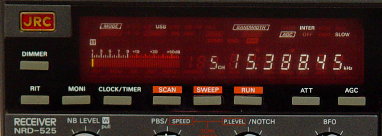
JRC NRD-525 Important Serial Number Information
If you are looking at a used Japan Radio Co. (JRC) NRD-525 Communication Receiver, here is very important serial number data to keep in mind.
JRC NRD-525 "Serial Number" History (sorry....the internal NRD-525 EPROM Firmware is not easily or is possible to be updated)
JRC NRD-525 "Serial Number" History (sorry....the internal NRD-525 EPROM Firmware is not easily or is possible to be updated)
- BR36471 (and above) SSB offset selection added
- BR36771 (and above) The tuning rate of the main tuning knob and the step increment of the UP and DOWN switches can be changed by hitting the RUN button. Selects the desperately needed 2 tuning knob speeds between 10 Hz or 100 Hz steps. The UP / DOWN slewing buttons toggle between 20 kHz and 10 kHz. Early samples only have a single VERY POKY and extremely frustrating 10 Hz tuning knob step.
- BR38301 (and above). The last important firmware update JRC did with the NRD-525.
HF RFI Generator - "Electronic Defrost Timer"
We had a defrost timer replaced in a near 20 year old refrigerator. The mechanical one that was in it was replaced by the Supco model UET120 which is of a solid state design. It creates some pretty nasty SW/HF interference with it's internal switching power supply (as I was afraid of). But it could have been worse. It’s RF noise in my situation (and is at a pretty major level) is between 2200 and 4000 kHz. It drops off greatly after that with only a very low level spur or harmonics above up to around 20 MHz.
Thomas Witherspoon of "The SWLing post.com" reports to me that between his refrigerator and freezer are the 2 worst HF RFI generators in his house. It appears that all new refrigerators / freezers are using these "el-cheapo" Chinese solid state "Defrost" timers now. These might seem more robust, but as I read around the internet they are not. Guessing are more prone to failure from spikes/power line surges ? Yeah, the new DX catch....the neighbors refrigerator.
Thank goodness I still have the MFJ-1026 device at HQ in case it gets too bad, but that is pain to have to deal with.
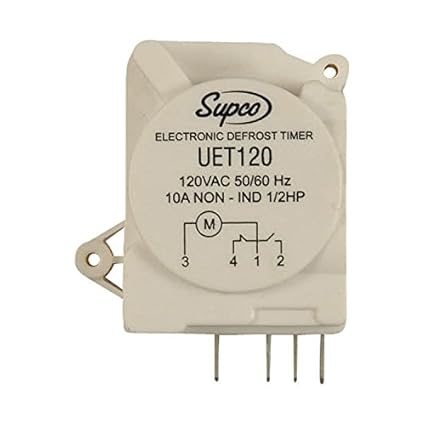
This time it's a "Solid State" Refrigerator Defrost Timer. We experienced this UET120 model by Supco.