|
N9EWO Review :
KENWOOD /
Trio R-1000
LW / MW / SW
Communications Receiver
|
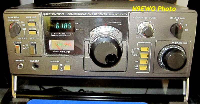
Kenwood
R-1000 Communications Receiver .
Manufactured in Japan from 1979 to early~mid 1986.
Also was sold as the Trio R-1000 in some parts of the world.
In our view it's the best
"Communications Receiver" Kenwood ever made for audio quality.
Many
used samples around are lacking the locking handle which works well as
a tilt bale. Cabinet paint scratches / chips extremely easy and the
main receiver PC board came in at least 2 versions. Only
Kenwood HF receiver that included 3 "stock" bandwidth filters. SSB
(narrow) filter is a 11 element "metal case" Murata CFJ455K5 (2.7 Khz)
. The W-I-D-E 12~15 kHz
filter allows for excellent audio quality when conditions warrant , and
also the WIDE filter selection adds a bass enhancement circuit to the
audio amplifier (except very early samples) . The set's excellent non
hissy - non distorted audio , good AGC (all modes, see text) , super
wide IF filter capability and large internal speaker, all give for the
best audio of ANY other set Kenwood receiver EVER made (in our testing
and view). No microprocessors
and only uses a PLL synthesizer. While fairly stable after a 1 hour
warm up , manual ECSS
is only OK (poor when cold). One can cheat the sets mode buttons to
allow use of the wider bandwidth
filters use in SSB modes (even allowing DRM reception without
any converter when connected to a computer with the DREAM software).
Uses no plastic gears or dial strings in the tuning system . (N9EWO photo)
Country of
Origin : Japan
Approximate "Test Samples" Serial Numbers
(3 samples tested for this review)
1st Sample : (owned mid 1980 , number was not archived)
2nd Sample (Made in Dec 1981): 112017x
3rd Sample (Made in Dec 1981) : 112017x
We have used / owned
the Kenwood R-600 , R-2000 , R-5000 and Yaesu FRG-7700 models for reference in
this report.
DISCONTINUED
RECEIVER
N9EWO's
Review on the Kenwood / Trio R-1000
Radical
Receiver Model for Kenwood in 1979 / Other Competing Models at the Time
in the Same Price Point - "No Match"
Prior to the R-1000 (which was
known as Trio / Kenwood at the
time), previous "solid state" HF receiver models were the QR-666 and
R-300 , both more simple analog designs (not tested and being older
designs are ruled out as being worthy in any comparisons here) . Were
also sold under the "Trio" name for some markets . In North
America were always sold under the Kenwood label. Frequency coverage in
the specifications is listed from 200 kHz to 30 MHz. However the
sensitivity is pretty dismal (as stock) for Long Wave and Medium Wave
uses (more later on this).
The R-1000 was released on the US
market in 1979. It was the
first communications receiver (at a reasonable price point) to feature
a "locking" Mhz band selector and getting away from tedious preselector
and Mhz band tuning which Yaesu and other "Wadley Loop" designed models
used at
the time (examples : Drake SSR-1, Yaesu FRG-7 and FRG-7000.). The
R-1000's design uses PLL
circuitry and was already common with JRC receivers of the day before
the R-1000 (NRD-505 and 515), but at a much higher price.
Yaesu
released the FRG-7700 in 1981 to compete , but is no equal to our ears.
Uses
the same tuning scheme and basic design and offers similar 3 IF
bandwidhs (including a
nice W-I-D-E one), but the outcome was not the same in our tests. We
detected the FRG-7700's audio loaded with IF hiss and is less
dynamic sounding. Yaesu did offer a 12 channel memory unit option for
the FRG-7700 which was rare for 1981 , but of course this type of add
on can only increase the
digital noise/hiss and decrease audio quality even further . But with
even without the option installed
the audio was no where near as good as the R-1000's.
IF Filters / Early Versions / AGC / Superb Audio Overall
"Out
of the Box" R-1000 IF Filter selections (all muRata Ceramic type)
AM
WIDE : CFW455F (6 element plastic case , 12 Khz)
AM
NARROW : CFW455HT (6 element plastic case , 6 Khz)
SSB
: 11 element "metal case" CFJ455K5 (2.7 khz)
In all but very early samples ,
Kenwood featured a IF "Filter
Select" 3 pin plug on the top RF-IF board (located near the 3 IF
filters ,
see photo below). This allowed the owner to choose between using the 6
and 12
Khz filter in AM mode (as it comes stock, and how we like it) or using
the 6 Khz filter in WIDE and the 2.7 Khz SSB filter for the AM narrow
selection (which we would never do).
No hiss, not muffled "woolly" , not
excessively bassy or overly sharp audio. SSB is near perfect as well.
Of course we have proper separate USB and LSB oscillators and is
extremely clean and stable. Only one note is with certain speakers
(more so with ones that have a tweeter) one might hear a touch of SSB
clipping distortion on certain signals. But this is being very picky
and most will not notice it.
With very early samples there will be no filter plug and no 2
sockets
as shown below for the filter change. However there was a modification
kit (BWK-1) that accomplished this but with no easy way switch back
over. Also
early samples had a extremely SLOW AGC decay rate . Our first 1980
sample
had this SLOW AGC capacitor and was awful. It too can be modified and
improved like later
samples (capacitor change) but might require
removal of the RF / IF PC board and that is NOT a easy task (with some
samples
this capacitor is on the rear of the mode switch). Even with the 2 late
1981 test samples with the updated AGC capacitor , the decay rate is
still a bit on the slow side, however we find this to be an
advantage and not a drawback. We very much love the R-1000's slower
lone AGC.
Also in all but the very early samples,
when in AM Wide IF filter selection only ,
there is a bass boost circuit that is engaged in the audio amplifier
circuit. Mind you this scant boost will not knock you out of the room,
but is most
noticeable and useful. Again depending on the speaker used, one may not here
any difference here at all.
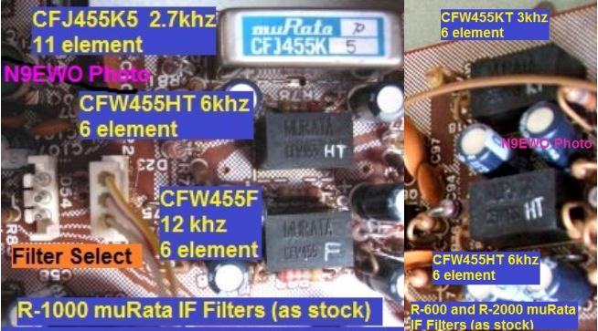
The
"three" STOCK R-1000's Ceramic IF Bandwidth Filters (left side of photo
above). The
R-600 and R-2000 models only included 2 filters and lacked the very
desirable 12 kHz CFW455F WIDE filter for fantastic audio when
conditions
warrant. Both other models used a lesser performing (and cheaper) 6
element SSB
filter . But the R-1000's above average audio quality is also because
of other factors in the design. The R-600 and R-2000 had much inferior
audio quality to our ears (as did the Yaesu FRG-7700) . Lacking
electronic switching (say for mode and bandwidth) certainly are pluses
to help keep general circuit noises down. The R-2000 in our testing was
awash with junk from it's very noisy microprocessor and contributing to
the generally raspy , hissy and tiring audio quality. (N9EWO Photo)
Decent Front End Filtering
The Kenwood R-1000 features "six" front end bandpass filters. These are automatically selected with the BAND selector knob.
They are :
0.2 to 1.0 MHz
1.0 to 2.0 MHz
2.0 to 4.0 MHz
4.0 to 8.0 MHz
8.0 to 16.0 MHz
16.0 to 30.0 MHz
Sensitivity /
Dirty switches / MW Attenuation
Sensitivity is right up there when I
even compare side by side with
the best receivers of today. However with any used sample, one MUST
CAREFULLY clean 5 switches with a good quality electronic switch
cleaner such as Deoxit
D5S-6
(ONLY use Caig D100 or F5 on dirty variable controls) and once in awhile do
general
maintenance on these 5 switches to keep full sensitivity (and this is
not that often if kept in at least intermittent use) . Be sure and
properly clean up the over
spray after (and protect as much as you can before).
***
These 5 Switches are ***
-
MHZ
Band Switch : Not so easy to force the spray into this switch however
(will take some work to inject spray into it's cracks).
-
ATTENUATOR Switch : Located in the right top of the RF / IF board near
the rear (follow the long shaft). If heavily dirty this may take
some additional soaking time and multiable treatments as I had to do
with one of the our used samples (it was stubborn as it sat for years,
before we cleaned this switch one test sample was not receiving
anything).
-
SW
ANT SELECT Switch : Located on the bottom section (rear) near the
SO-239 antenna connector. Can get as dirty as the ATTENUATOR switch.
- FUNCTION Switch : (Long switch Top left
side front) : Not as problematic as the 3 above.
-
MODE Switches : Actually this is a bank of them. More that are not so
easy to get cleaner into. But are not always problem switches.
The
R-1000 uses a dual up conversion super heterodyne design, with
balanced MOSFET circuits being used in BOTH mixer stages. One may start
to
compare to the lower cost R-600 which came out in 1982 touting TRIPLE
conversion. But the R-600 sold for less dollars and it showed. Hissy
and fewer bandwidth selections (with a low cost SSB filter and NO
desirable super wide filter offered). Also the main tuning capacitor
was
of lower quality along with inferior PLASTIC tuning gearing as well as being a much
less stable design (so excessively drifty). The R-2000 model while
sporting full microprocessor operation, was awash with hash and hiss
for not so great audio. They also suffered
from the same lousy included IF filters and just a plain disappointment
to our ears
(including the cheaper plastic SSB filter).
As with many Kenwood and Icom receivers, the R-1000's Medium Wave
input
circuit (0 and 1 on the BAND selector, so up to 2 Mhz) includes an
Attenuator to reduce overloading. This consists of 3 resistors in the
case of the R-1000. It is NOT selectable and always active. There is a
modification around the internet to remove this attenuator, but
depending where you live this might it not be a good idea. We have NOT
tested this modification and can't say one way or the other how well
(or not) it works. As stock MW sensitivity is poor. NOTE : It has been
said elsewhere that the reason for the MW attenuator to help keep MW
signals from ghosting into the SW spectrum. With our unmodified stock
sample, he have yet to hear any local MW station intrusion.
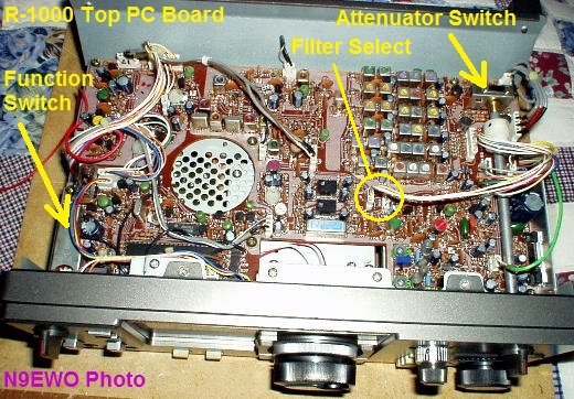
The
R-1000's Top RF / IF PC Board. The white plastic coupling piece that attaches the
long ATTENUATOR shaft can become loose in time. Be careful over
tightening it's hex set screws as it can crack very easy and
replacements are hard to come
by. Same goes for the MHZ BAND knob. The main tuning knob is a push on
affair. (N9EWO
Photo)
|
WARNING : I
will NOT be held responsible for any information that is listed here.
ALL DONE AT YOUR OWN RISK !
|
Power Supply Bug-A-Boo's / Loose Antenna Connector Common / Quite
Stable After Warm Up
As with many Kenwood HF receivers, the internal power supply runs on
the HOT side. It's not so much the very nice shielded power transformer
where the majority of the heat comes from. It's the components on the
power supplies PC board "heatsink" that gets near too hot to touch
after some time in operation. We have never seen any failures of any
the components on this PC Board, however in time the connections in
general can become very flaky to non existent. One very common
complaint is the receivers frequency counter goes floating all over the
place or a fixed 39.545 Mhz display . Also the receiver may experience
excessive drift. This is usually because the 5 volt output has failed
or near failed on
the Power Supply board. Most times this can be totally fixed by just
re-soldering all connections on the Power Supply board. Will need to
remove the mounting screws on the this Board and at least remove the
long white plug. Flip it over and using good old fashioned LEAD type
solder (avoid the Lead Free stuff), reflow the connections. Notorious
bad connections are on that long connector socket pins closest to the
heatsinks (dual 5v + connections). But just re-solder the entire board (see additional information on the bottom of this page).
Not saying this might be the only problem that can crop up, but is the
most common one. Some have reported the main power supply capacitor has
failed, but I have yet to see this with any of my test sample and
friends R-1000's.
Loose SO-239 connectors are common on all Kenwood receivers and
transceivers that use (what I call) the strange single "wavy mounting
nut" .
Not so easy to tighten. Just about every used R-600 / R-1000 / R-2000 I
have
encountered has had a loose SO-239 antenna connector. See photo below
for a picture of this.
The R-1000 is quite stable after a warm up period. I would say near an
hour for really decent stability. Mind you (manual) ECSS reception
which is possible even being very touchy to tune in, still tends to be
a little drifty for that use (but still usable). Remember the design is
microprocessor free .
Inconsistent Florescent Display Quality
One MAJOR quirk that I have observed with the Kenwood R-1000 since day
one on various samples is the brightness / quality of the FUTABA
5-BT-05 florescent display used varies greatly from sample to sample.
That is some segments of a digit can be severely diminished , or one
side of the display can be brighter than the other. This quazi
defect is more noticed with the "Dimmer" on. Not to say this issue have
not inflicted other sets over the years that use florescent displays
(it sure has), just that Kenwood did not have much of a rejection curve
for semi sour looking displays in production. Some samples look perfect
in this regard , while others are not so hot.
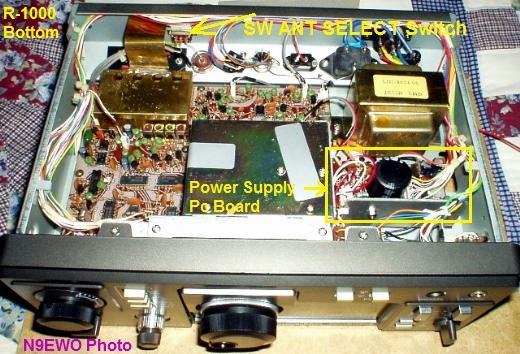
The
R-1000's Bottom PLL Synthesizer and Power Supply PC Boards. There
are NO microprocessors in this HF receiver. NOTE : The "Service Manual"
calls the Power Supply PC Board as part of the
PLL Unit. (N9EWO Photo)
Dynamic
Range / Image Rejection / Spurious Signals / Noise Blanker
Dynamic range (freedom from overloading) is adequate . Not to
say that it cannot happen with powerhouse short wave signals say on 49
meters at night connected to a good outdoor antenna. The first click
(20 db) of it's RF Attenuator does the trick to squash this. But not
too often that is required (at least with our antenna's). Even by
todays standards it's not bad at all. However I do remember our first
1980 sample having more overloading issues ?? So perhaps changes were
made with later samples ??
Image rejection is equally decent. No ghost signals appear 910 kHz
away. However there are strange SW spurious signals that do crop up
when signals are the strongest . Signals from VERY STRONG lower
frequencies (say at 6 and 7 MHz) pop up in the 14 and 15 MHz area.
Never grasped what is going on here, but I would not call it
overloading . But again the RF Attenuator fixes this and is another one
that only rears it's ugly head once in awhile. Perhaps this has
something to do with it's limited front end filtering (which it does
have) ??
Noise blanker is by late 1970's standards. Not adjustable and it's
either on or off. It can be useful for some power line or other
electric buzzes. But it will need to be on the stronger side to have
any effect. Sometimes it helps, other times it does not.
Cheat The Mode Buttons / DRM Possible Without Mods
You say you wish you could use the AM "NAR" and "WIDE" in SSB modes ?
Being the MODE buttons are of a mechanical type, that's no problem .
Just push either of the SSB buttons in along with the AM Mode "NAR" or
"WIDE" at the same time and that's it. It is a bit tricky to get both
buttons to lock into place , but it works. Also comes in handy when I
doing ECSS reception. But due to the not so perfect stability, it's of
only minor use here .
When SSB is used with the "WIDE" (12 and NOT 6 kHz) AM Filter and
plugged into a computer running the DREAM software, we were actually
able to get DRM broadcast to decode after some fine tuning. This is
without any modifications or other add ons to the receiver. But proper
audio connections are required to have any chance for this to work (see
the Record Output Jack connections below).
A Real Frequency Counter /
SSB Readings Will Be Off
The R-1000 uses a real frequency counter LSI IC (oki MSM5524) .
Our first 1980 sample (which was a early manufactured one purchased
brand new) suffered from inaccurate counter readings. It was dead on at
one end of a MHz band and by the time we tuned to the other end it was
a good 5 KHz off (AM Mode). This turned out to be a misalignment at the
factory (sample was made during the shake down cruise I guess). Our
current
, Dec 1981 sample is dead on anywhere I tune it.
When tuning SSB modes the counter will be off. This is not a fault and
totally normal as the counter is only accurate with AM carrier signals
(it's in the design). So for a little math and this may vary slightly
depending on any given sample. But you get the idea.... :
R-1000 Display
Offset When Tuning SSB
USB : Subtract 1
kHz from what the display indicates
LSB : Add 2 kHz
from what the display indicates
Record Output Jack
- Is at Mic Level (Not Line)
The RECORD jack is mounted on the
FRONT of the receiver (1/8 inch mono phone jack) next to the 1/4 phone
headphone jack. Is slightly recessed. Has a very clean unbuffered
output and is at a low MIC level. That means that it needs to be
connected to a MIC input of any recording device or computer (a
standard line level connection is too low and will not work). We need a
line level for our audio switching system for other receivers, so we
added a ROLLS MP13
Mini-Mic preamp and this worked perfectly after adjusting the
gain with
it's level control to match our requirements (this will also work for
the Sony ICF2010 / 2001D and other OLDER Sony SW sets as well ).
NOTE : The Bass Boost circuit in the WIDE bandwidth is not seen at the
"Record" output .
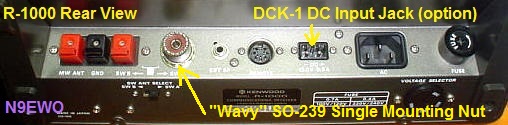
R-1000's rear panel.
The "DCK-1 13.8V DC Input Jack / Cable Kit" was optional and now very
rare on the used market.
The 3 spring clips on the far left (MW-GND-SW B) are notorious for not
pushing in and breaking in it's old age.
Best
HF Receiver Kenwood Made For Audio Quality in Our View / They Have Held Up Well
Over The Years (Properly Treated)
Have also tested the R-5000 model (review click here) and in our view with it's lack of the the WIDE 12 kHz bandwidth filter, we strongly feel that the R-1000
is the best HF receiver that Kenwood ever produced for audio quality. It has held up
better too with age and not one dial string to break .
True, it lacks the fancies of a RF Gain control, Pass Band Tuning, Sync
Detection, Notch Filters ,
Memories (which were very rare in 1979)...etc etc . But the simplicity
is another part of the set that made it very special yet still provide
performance with excellent audio quality.
As it goes with any vintage receiver, the used market is awash with
good samples and also ones that look like they have been through a few
dozen wars.
There are normally used R-1000's on the used market frequently as it was in production for over 6 years.
Dave N9EWO
© N9EWO, all rights reserved
ver 3.5
DISCONTINUED
RECEIVER
LINKS (All Subject To
Change Without Notice)
eham R-1000 User Reviews
Kenwood
R-1000 Service Manual (PDF)
Trio / Kenwood R-1000 Receiver : groups.io
Kenwood R-1000 Owners Manual (PDF)
| Kenwood R-1000 “39.545
MHz” Display Repair |
After
years of operation the Kenwood R-1000 can suffer a fixed 39.545 MHz
display and/or a dead/intermittent radio/display. First place is to
check and re-solder joints at Q201 and Q203 on the small power supply /
PLL board on the underside of the chassis. This is where connector # 12
is located. The two TO-220 devices mounted on the large heat sink and
the PC board solder connections can work loose after many hot / cold
cycles.
Also be sure and re-solder / touch-up all of the solder joints
involving connector # 12 and the 4-power rectifier diodes as well as these can
cause for bad connections too (might as well re-solder the entire
board).
Pay close attention with pins one and two (on connector # 12) as these
are 5 volt pins closest to the HOT heat sink. They may look OK, but in
many cases are not. In extreme cases all of the electrolytic
capacitors, Q201 and/or Q203 and/or the 4 power rectifier diodes may need
replacement on this PC board (but this is rare). See the service manual for
more details (link above).
Dave N9EWO
© N9EWO, all rights reserved
ver 4.0
WARNING
: I will NOT be held responsible for any information that is listed
here.
ALL
DONE AT YOUR OWN RISK !
|