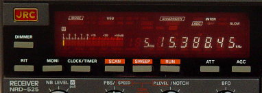
| N9EWO Review : Japan Radio Co. JRC NRD-545 DSP Receiver |
Discontinued Receiver
N9EWO's
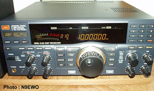
Review of the Japan Radio Co. (JRC) NRD-545 DSP (HF) Receiver
User comments have been at the extremes from excellent to "really
poor" with the JRC NRD-545. Of course it has more to do on
how sensitive YOU are to the DSP noises (overloading)
that this set can emit under certain conditions. Actually it's
"Audio Recovery" , that is pulling a person's spoken
word out of the mud, is quite good. This is a superhet design with DSP used in the IF / DETECTION / AGC etc. I have owned 2
samples (plus a Sherwood test sample), all being the latest
firmware.
A few off the newsgroups have indicated that I do not have my NRD-545
receiver set up correctly, so I'm hearing those noises that I
have indicated below. NOT TRUE !!! I
have quite enough hours using this set over the years to tell you that
these sounds (DSP overloading) are no
joke no matter how you adjust it. It very well depends on where
you are, what antenna you are using, what time of day you use the
set, signal activity/strength around the tuned frequency...etc.
Many factors play in this and will not be the same for all. Again,
just be aware if you plan on making a "used" purchase
of one.
The last "new" NRD-545's were manufactured in early 2008. So it's the used market for any purchases of this model. Be sure and read the "mute" issue text at the bottom of this web page in the "green" block, it can be a real issue with some used samples as well as aging CCFL LCD backlights.
Three
samples were tested for this report
First Impressions
The quality of construction is in the usual JRC tradition, "excellent"
inside and out. The "internal" power transformer is of
good quality too, I think the same one that was used in the NRD-525 /
535.
It is very quiet and normal amount of heat. No excessive buzzing
sounds (unlike the power transformer in the
NRD-301A test sample, which
buzzed like a hive of mad bee's, also ran very HOT).
Also JRC did a excellent job with the rest of the power supply as
well. They are feeding the input voltage to the 545's regulator's
at a perfect level (as was the case in the NRD-525-535 sets), so
they run at a very good "warmish" temperature. I have
heard of Drake not doing so well in this area with the R-8 series.....you
will NOT have to resort of having to use a external DC power
supply to run this receiver (as some Drake R-8x owners have
done) because of excessive heat and or excessive "buzzy"noises.
UPDATE : JRC changed the power transformer in later
production, see green block below.
A mechanical rotary encoder is being used for the "BWC" control
and has a very good feel to it. The tuning knob also has a very good
feel to it, no weird play or grizzly feeling. It indeed uses a
very good optical type encoder here, and at this price point it should.
Push buttons all have a OK feel and are of the "tact"
switch variety. Thank goodness no "Rubber/Soft Plastic" key's
! A bit of "looseness" and key wobble which is normal
using this system.Yes, the 545 has the painted pushbuttons just
as it was on the NRD-535. I wish manufactures would get away from
the use of painting the surface of the actual button that we will
be placing our paws on. You know these could show wear and worst
case this paint will get removed with use.
General ergonomics are of the usual JRC stature, superb. The
“Tuning Knob” speed is much improved over the NRD-525
and 535. I can set it to the speed what I like. It was just too S-L-O-W
on these other JRC”s sets. My old NRD-93 also suffered from
a even slower “turtle” speed knob. More later on this , but much better
JRC...thank you.
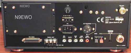
As with the NRD-525 / 535 ,
the NRD-545 is using a nice standard "computer type" 3-wire AC plug
socket for the
power input, another great item to see.
Display is a Negative Type LCD and uses a
Fluorescent Tube behind it (Cold Cathode Florescent Lamp) for the backlight. These WILL fail
sooner of later in it's old age and parts are no longer available, so
be warned. When you first turn on the NRD-545 from a cold start, the
display
brightness will be dim for the first couple of minutes or so. This
is totally normal for a CCFL backlighting system and is not a fault.
I wish JRC would have included at least a basic set of schematics
with the set . It's another "shame on you
JRC thing". All we get in the owners manual is a lousy block
diagram. A step back here in my view as they used to on all other
previous sets (except the NRD-345). The excuse "well just
purchase the service manual" does not wash with me !
|
Internal "AC Power Transformer" switch made in later JRC NRD-545 samples. |
|
I made a note above
that the internal power transformer in the NRD-545 was of high quality
and made no detectable buzz/hum noises even with it off (a very light
load when off). Well this changed at bit with later
production. John W. has told me that his early 2006 sample's
transformer buzzes even with it off. It's a minor issue with him. But
it appears that JRC are using a different AC power transformer with
later samples, either with the manufacturer or at least the style.  Pictures of the 2 internal AC power transformers that have been used in the JRC NRD-545. The newer one on the left is reported to buzz more with even a very light load (radio off). The one in my late 1999 sample is as quiet as dead mouse and generally low heat. NOTE : We have not tested a sample with one of these new AC transformers. (2006 photo via John W., 1999 picture via N9EWO) Being I have not tested one of
these new samples to "hear" how bad this buzz may be, I have to stand
neutral on this one. I guess look for a used sample for sale that has
the older "green" transformer if this is super important to you ? Issues with noisy power supply transformers in a receiver are a real sticking point with me and is totally unacceptable. Don't get me wrong, I love having a GOOD internal power supply in a receiver, but not if it's going to create a nasty buzz within the room. Caveat Emptor if this is important to YOU !! .....Dave N9EWO |
CHE-199 Converter
Blues !!!
On the first NRD-545 test sample, I purchased the CHE-199 VHF/UHF
Converter Unit. It installed very easy with no real tools. Just a
slide in board and one little coax connector that pops on fast.
Well after doing the required reset, It did indeed come to life,
on the display that is. As far as RF performance, it was totally DEAF
(near zero sensitivity) ! This was connected to high performance
antenna’s as well. It barely received my local 20 kw FM
broadcasting station . For any local amateur radio signals...Nothing
!!...Nada. I have heard of others with this same problem. But
good news is for most folks the replacement did indeed work just
fine (I did not get another one to find out for myself).
It seems that JRC just had an above average “dud” rate
with the CHE-199 converter ? So if you experience “Nada”
instead of your Local PD....you could have one of those bad ones
?? I hear the performance is nothing to scream about when it does
work right. I say forget the CHE-199 !
|
I
will NOT be held responsible for any info that is listed here |
CGD-197 TCXO, Beep
Level and Adjustment.
First job I wanted to tackle after dealing with the converter
DOA business , was to install the CGD-197 TCXO option (Temperature
Compensated Crystal "Reference" Oscillator) . Be sure to
remove the little foam strip that all JRC owners all know about
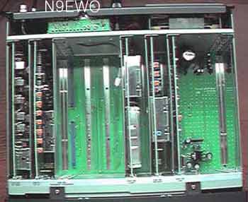
which hold the boards in place during shipment. But what
hit’s you the fastest is the fact that ”where are
innards” ? It certainly has fewer boards than previous JRC
receivers. More of the sets power is being done within the DSP so
the parts count is much less.
I found that the "Beep" level was too loud for my ears.
There is a "Beep Level Volume" adjustment (RV3)
located on the top of the CGK-160 REF/DDS board. Of course you must
have the set powered on and connected to an external speaker to
make this "tweak". This is covered in the
owners manual as well. Yes, I wish to have a beep feedback, but
not so
loud.
NOTE :
If you do make this
adjustment, be very careful NOT to adjust with the 2 'line output'
trimmer controls by mistake that are right next to this "Beep"
adjustment. Will be very hard to get these back to factory specs
without test equipment. Use a flashlight and be sure that your
are on the right control in the first place !!
“Frequency
Display a bit off.....out of the box”
This is a gremlin with tabletop HF receivers that drives me nuts, and
was the
first item I corrected before I put the set to real use.
On the 2 samples that I have tested / owned , both were off out of the box
by around 20 to 30 Hz. This is not a nasty problem, but if you
are off by 20 hz at 5 MHz, it will be worse at 15 MHz. So if you
are dead on at 15 MHz...will should also be so at 5 MHz (well it
should work that way). So if you are off a bit and wish to be at
least closer to dead on you need to adjust CV-1 on CGK-160 board
(as indicated on page 31 of the manual). Note: The higher you do
go up in frequency the more touchy the adjustment (CV-1) gets.
But try and adjust using WWV at 15 MHz.
WARNING:
You want to pass on this adjustment if you do not have lots of
patience. It can be very time consuming and end up with it even
being worse !! As usual...Doing ANY of these
adjustments are done at YOUR OWN RISK !!!
I use a bit different method to achieve this adjustment than
listed in the owners manual. You must use a "Strong" signal on
WWV on 15.000.000 MHz as they
are transmitting those nifty tones (don't try if it's weak or
during a quiet periods in the hour), being selected at the "Local"
SSB shift (default anyway), and using USB / LSB (NOT CW as in the
manual), I turn the BWC to a W-I-D-E bandwidth of at least 6 KHz
or above (might as well open it up and use 9.99 KHz). Then you
are able to hear the "off beat" tones real well. Makes
adjusting CV-1 much easier. Allow the set warm up at least 1 hour
before you do this. Of course use a hi-fi pair of headphones or
external speaker to hear the output. You should hear NO
difference what-so-ever between USB and LSB when it's adjusted
correctly. If you cannot hear WWV (or WWVH) well at your
location..sorry
to say I don't have any other idea's for you.
|
I
will NOT be held responsible for any info that is listed here |
"Adding the
CGD-197 TCXO"
Now you might say well, just add the CGD-197 TCXO option and that
should clear up that problem...well not quite. I have installed a
couple of these and both were off, a bit closer to the stock installed
reference crystal....but
not by much. Still about 20 Hz off (high). I can understand how
this can happen..too many factors that can throw off a part like
this and it's going to vary from set to set that it is installed
into, bounced around in transit as well as normal aging of the
crystal itself . Remember the TCXO was standard in the old NRD-525
.
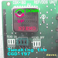
As you can see in the picture below, there is indeed a trimmer
cap on the CGD-197. But how do you get to it ?? CV-1 trimmer only
works on the internal reference crystal. Well it can be done (I do not
have
any test equipment or the extension board) , but it's the old ..PULL THE POWER
PLUG FROM THE WALL SOCKET EVERY TIME !!! (THIS IS MOST IMPORTANT)...pop the CGK-160 board out..do your
adjustment with the proper tool. Stick it back in and see how you did.
Of course
allow say 10 minutes here for the crystal to reach correct temp. You of
course have to keep doing this until you get it right....huffda..!!!
Time consuming is right.
Another WARNING here...this is a VERY VERY touchy variable
capacitor. Again this can be a very time consuming and mind
straining procedure. Avoid this if you have problems with
ventures like this, leave it with it being a bit OFF.
After installing a 2
CGD-197's and these adjustments....on the second time around I
had it "Dead On" in a record 15 minutes. Now if I select
10,000.000 MHz , I actually get it. This is a big plus tuning
manual ECSS (using USB/LSB), provided the station is on frequency.
And of course I can check a station's frequency quickly and
really see if they are off which can help to ID a station.
But
alas, even after an additional time period (a number of years
since I installed it), it has again moved up in frequency (10 hz),
so it appears a touch up every once in awhile may still be needed).
1000
Memories, 32 User Defined Functions, Memory Battery, User Defined
entries a bit
tricky to the novice, Speed up the BWC step.
We have 1000 memory channels available on the NRD-545. Each memory
channel stores: Frequency, mode, IF Filter Bandwidth
(what you have stored in the WIDE, INTER or NARROW preset buttons),
AGC,
ATT and Tuning Steps. It does NOT store the ECSS function. The
bandwidths can also be adjusted on the fly, not having to default in
the menus either (unlike so many other DSP receivers and transceivers).
For the “IF Filter
Bandwidth” presets in each memory entry, it
will store the WIDE, INTER or NARROW button. So what you have
entered in these 3 presets is what will end up in the memory channels.
You can easily change these from default for the 3 bandwidth presets.
My
favorites are listed in the charts at the bottom of this report (no
suprise that they are on the wider side). See page 9 of the
owners manual for the details, but remember every mode has different
default settings.
IMPORTANT USER TIP : To make the Bandwidth
knob "steps"
move at a faster rate (100 hz steps vs 10 hz default) by pressing
the FUNC button and then BWC. Whew, now that's much better.
These Bandwidths defaults are changed by hitting the FUNC key
then push the BANDWIDTH button that you wish to change (WIDE,
INTER or NARROW), next rotate the BWC knob to your desired
bandwidth and finally push ENT/kHz to seal the deal. Again, every
mode has it’s own settings.
32 "User Defined" functions are found on the NRD-545. The chart at
the bottom of this page covers what these are and my recommended
settings . But these can be a
bit confusing for PROPER entry in the NRD-545 for the
“novice”. The manual is a bit confusing (at least it
was to me for the first time), and if one does not do this in the
correct procedure, the entries will not take. It’s a piece
of cake once you get use to it.
1. First press the FUNC button, followed by ENT/kHz. You will see
001 FLASHING on the left and what ever number is stored in this
User Defined entry in the middle-right.
2. Next rotate the AGC/BWC
knob to the desired entry number (number at left, it should be
flashing as you rotate it).
3. Press the ENT/kHz button
again, now
the flashing number with move to the Middle (ok lets call it to
the right).
4. Rotate the AGC/BWC knob
to the desired number.
5. Press
ENT/kHz again. The Left number will be flashing again (this is
what will be changed when your rotate the knob).
Repeat for other entries, but when you are finished be sure to
end up with the left entry numbers flashing.
6. NOW the important
part, hit the CLR button when totally finished. Maybe this is not
totally correct, but is what works for me.
IMPORTANT NOTE : With any entry like this (either
“user defined” other entries) on the NRD-545, one needs
to keep in mind is if you go 15 seconds without a keypad
“press” or knob rotation, it will revert back to a
normal display and you will need to start over. If you allow this
to happen, none of the entries that you have made may not take?
“# 32” User Set-Up
Function (DSP Filter)
One item that you might wish to change in the “User Set-Up
Functions” right away ?
On # 32 Filter setting I made the selection as 1: DSP
LOOSE filter. It is set out of the box (Default) as...0:
DSP SHARP filter....I found the audio more harsh, more so with
fading distortion (even with ECSS) in default "0".
However "SHARP" does give slightly better audio
recovery to my ears. So depends on what type of signals you are
listening to? With broadcasting stations (MW or SW) "LOOSE"
was better for me in the AM or ECSS modes. Using the wider
bandwidths this is less of an issue.
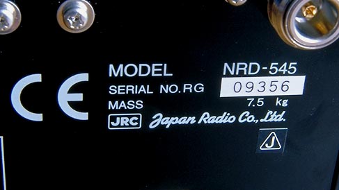
What's that "Serial
Number" business again ??
NRD-545's with a serial number of RG 04665 and
above have the latest ROM firmware (both DSP and operation EPROMS).
The earlier samples had dreadful audio quality. What you read in
this report/review were with 2 sets that have serial numbers
above RG 04665, and of course the latest firmware.
"Audio in the Ruff”...DSP Limitations
?
But the first time I really listened to the audio of this set...I
was pretty sad indeed. But now that I’m more used to it’s
different traits, it’s not as much of a factor and not a major quirk
(but it still
can be annoying depending).
The 2 types of weird sounds that the NRD-545 emits are a bit hard
to explain. One being more of a burp sound, the other is of a
“Tick Tick” sound.
A comment made by Chris Lobdell explains a bit more on this:
"Another flaw--and I have no idea what the cause is--is a
"clicking" sound that occurs while listening in the AM
mode. It does not occur on all signals, but tends to show up on
signals that are moderate in strength. The clicks tend to be
about two per second, and are loud enough to detract from the
enjoyment of listening"
Now to be fair, these gremlins only appear on ..oh I would say 1
in 20 signals, not on all . But when it does, the DSP garbage
really shows it's ugly head. 2 types of "weird" sounds
!!! There was NO local interference at all when I heard thee
noises and again NO NB or Notch filters were on !! ECSS was off
as well. Most important...if you switch over to ECSS (manual or
Auto)..most of the time (but not always) the gremlins can sometimes go
away.
So depending, maybe a way around it...but really should we have to hear
this at all coming out of near $ 2000. communications receiver ???
| NRD-545 DSP Issues - N9EWO MP3 Audio Files (as recorded off test samples) |
| "DSP Burp's" (0:05 sec mp3 file) Vatican getting ready to sign on 7305 kHz with a dead carrier. As the signal rises and falls..shows the annoying DSP Burp issue "DSP Tick Sound" (0:15 sec mp3 file) This mp3 audio file shows equally annoying tick sound. |
Adding to the audio blues in the virgin AM mode...fading distortion sounds very harsh than with others receivers I have ever used. Another "hard to explain" problem which I can only notice on stronger signals (and still only once in awhile) with a certain fading patterns, is what sounds like an overloaded audio signal for a second or two. Manual or Auto ECSS modes usually (but not always) clears up these problems.
So for any AM Broadcast signals , you need to use ECSS (manual or automatic)...otherwise it can be very irritating indeed. There is slight hiss coming from the audio amp in the set too. This can be a bit annoying depending on the speaker (or headphones) being used, but does not creep out of the line outputs.The (Sync) auto ECSS circuit in general works well, only looses lock for a split second on the worst of fades..not very often. But the best Sync-ECSS in a JRC set. As you might remember the auto ECSS circuit in the NRD-535 "D" was a awful performer. The "Sync" (Auto ECSS) in the NRD-345 is another poor circuit.
IMPORTANT
USER TIP : The closer you are to the "CENTER" of the
carrier, the better it will hold lock. Do not try and use the
Sync-ECSS mode if you are not tuned correctly tuned to the center of
the signal.
After a bit more experience using the Sync-ECSS on the 545, it
can indeed loose lock for a split second on strong signals very
deep "sharp" fades.It seems that the stronger the
signal, it will have more of a chance to loose lock for that
split second ?? Weird is right. This is not a serious flaw...but
can be annoying on certain strong signals. More times than not,
it works just fine. Sync-ECSS is still better than any previous
JRC receiver.
In general the audio quality is no great
shakes (fair at best). Better than ANY other JRC receiver mind you (and
I have tested most major JRC receiver models) , but that is not saying
much even with a better speaker attached (see below).
AGC is NOT Adjustable in AM or Sync-ECSS
Modes
The AD's that JRC had floating around on the NRD-545 when being sold
new, indicated
that the AGC decay rate was adjustable in the Sync-ECSS mode. Well
if they are talking about the auto "ECSS" button/mode..they
are DEAD WRONG , as it most certainly is not. It is fixed (not
adjustable) just as it
is in the AM mode. Yes, this is correct...you are NOT able to
adjust the ACG decay rate in the AM mode with the NRD-545.
Slight Sync-ECSS "OFF" Gremlin
One note I need to pass along in regards to the Sync-ECSS
mode.
IN SOME CASES, when you
turn off the Sync-ECSS
and start to tune with the knob, you may notice that it may not
be totally OFF (you may hear heterodynes). So once in awhile
it can take about 5 seconds for other circuits in the ECSS
circuit chain to totally turn off. So 2 or 3 "Mississippi's"
you will hear the "het's" go away. This is not a fault
and is totally normal.
What is the "AMS" button for ?? (for you first time
folks to the NRD-545), SW stereo
On the "AM" mode button, you see AMS printed along
side of it. The owners manual gives very little information on
what this function really does. Well first it appears to give a
even wider IF bandwidth over what the normal BWC control gives at
max (10 kHz). I would say about 12 kHz here, but that's a guess
as no real spec's exist.
If you are tuned to stronger "in the clear" signal with
no fading (say a MW station) it can make for a real aural treat.
If not , well that break up distortion can create a painful experience.
Also the Sync-ECSS does not work when AMS is on, so no
way to tackle the problem other than to turn it off.
But the real reason for the AMS button is the fact that it
toggles the AM
STEREO function (Motorola C-Quam system) Again,
you have no Sync-ECSS function when the AMS button is on, so is
not always good news here.
Overall it's fun. However, to hear this Stereo output (also
goes for FM stereo when the converter is installed), you MUST
connect the L and R line outputs to a EXTERNAL amplifier (or
amplified computer speakers will work too).
Of course this was intended for MW stations, but IF a
SW broadcast station broadcasts a C-QUAM signal , the NRD-545 will be
able to decode it. A North American
pirate has actually used C-QUAM on SW from our
own monitoring and works good as expected (listen here as recorded
using the NRD-545). But this the only example we
have heard this used so don't look for much use on SW.
Tone Control affects “Line” Output
The "Tone" control affects the "Line" audio
outputs. Yes..you could have knocked me over with a slight breeze
when I first discovered this. Not a bad thing here...if you have
a signal in the mud and are trying make a recording of it..this
can be a big plus. Now that I see after doing a bit of reading in
the brochure, the tone control is indeed adjusted via the DSP
chip. Good idea here and works well.
General “Volume” quirk
One little minor quirk is that on certain "Broadcast"
stations that are low in the audio dept the NRD-545
seems to have a hard time keeping up . That even with the volume
control at 3 o'clock, you still may not have enough audio to hear
it right. So the comment we have seen made by other users (see bottom
of this page)..."It can run out of volume control"..seems
to be a very true statement. The very expensive (and also
discontinued) JRC NRD-301A "Super Set" that I
have also tested has this same trait. This is the first 2 receivers
that I
have ever encountered that is weird in this way ?? Again, only a
minor problem that should not make you shy away from this
receiver...but for the record, you now know about his.
Is that 4 or 8 ohms with the speaker output ?? , Realistic
Minimus-77 External Speaker
Well could be a part of the above "volume" problem ??
Just about all JRC receivers are rated 1 Watt at 4 OHMS . Yes
4 Ohms !!! Using a 8 ohm speaker is not going to hurt a thing
(other way around could be). Matter of fact the matching (and
suboptimal) NVA-319
speaker is using a 8 ohm speaker inside . But the output might be
cut back at least a bit using a 8 ohm speaker, where a 4 ohm
might give a extra kick ?? I have not tested this, but could
be something to look into ??
The only JRC set that I have noticed that is NOT listed at 4 ohms
is the NRD-345. It is listed as 8 ohms. Weird to sat the least,
and I'm not sure how much I want to believe this ??
But could be one of the reasons why some JRC owners (me included)
have had sour luck in making some external speakers work right ??
I used a SMALLER OLDER 2-way die-cast hi-fi
speaker. For me it's the Realistic Minimus-77
cat # 40-2054 from the early 90's. The tweeter helps very much here
along with the larger woofer over the smaller Minimus 7 cousin. NOTE: I
have tried all of Radio
Shack's (including the RadioShack branded RCA ones) more later metal
die-case 2-way
speakers and they all
required too much audio
power to drive them (so that was a total bust). These older 40-2054's
do not have this problem for some reason. Tip : If you hunt for one
these speakers on the used market , watch out for the foam
deterioration on the woofer.
"Quick Toggle" of Front End Filters
Something that I discovered that was NOT indicated in my
545's owners manual. This was on my NRD-545 with a serial number
a bit over RG 06400 and may or may not exist on older or latest
versions (not sure) ??
On # 24 of the "User Setup Functions", we have a
selection for front end filtering . This allows you to bypass the
front end filters for perhaps a bit more sensitivity in cases
where you need every bit to pull a signal out of the mud.
Normally front end filters (preselector filtering) can give a few
db's of signal loss. But of course you should NOT leave this in
the bypassed mode for normal listening. The NRD-525's and 535's
also have the same "pass" switch.
But during "scan" (scanning of the memories) function,
leaving these filters on and as it chuffs over the memory
channels...well it makes the filter relays chatter like a old car
on it's last legs.
So to switch off the front end filters you have to dread to the
"user setup function" mode. Select it down to # 24, and
then switch it to 0. Of course after you are done with your
scanning, you have to do this chore all over again.
Well here is the "quick toggle" that I discovered.
Press the "FUNC" (function) key then the "ATT"
key. You will hear one beep (not the usual error beeps). You will
see NO indication on the display anywhere, even if you drop into
the user setup mode and peek at # 24 after you do this, it will
not show it correctly. To toggle it back, just repeat "FUNC"
and "ATT" again.
If you turn off the set and turn it back on again, it will
default to whatever you have set in # 24. This quick toggle
operation will not change this setting in any way.
I miss the "pass" indication on the display with the
NRD-545. The NRD-525 and 535 had this of course.
(N9EWO
with another neat finding on a JRC receiver. Remember the 99.999.99
entry with the NRD-535 ,as listed in
October 1991 Monitoring
Times page 107 ..."Display Test Mode" . The NRD-545 display mode
is selected by
while pressing and holding the FUNC + DIMMER buttons , then power
the receiver up. To switch back to normal mode, just rotate the
tuning knob.)
I love the IF bandwidths adjustable up to 10 kHz (or more). I hate
receivers that stop at 6~8 kHz which seems to be the trend these
days !
So what's the word / Discontinued
Receiver / CCFL Failure Possibility
The AGC configuration and adjustments with the 545
is excellent for SSB signals. AM mode with the "lone" fixed AGC is not
as stellar , but is most usable for the most part. SSB audio actually
sounds much cleaner and less hisser than
with the AOR AR7030. Overall audio quality is still a
disappointment in our view.
After reading these comments you are wondering if I'm totally against
this set ? No. I actually enjoyed
the NRD-545, just took awhile getting used to it's strange traits ? If I hear
the DSP gremlins getting into a
signal I'm really trying to hear right or even more important
"record" , and depending how serious it's destroying a
signal....I might have to switch over another set. But really
why should I have to do this right ?
Reliability, quality of construction
, most parts used (with
the exception of the VCO trimmer capacitor failures for some owners)
and of course the general overall design were all well above any
other consumer tabletop set at time this receiver was released on the
market.
With all of the problems the AOR AR7030 has had over the years (and
was until the end of it's production), it's just a more
refreshing experience even with the audio (DSP) issues and general
audio quality.
I have had my hands on many JRC
receivers over the years (including the professional models, see the
main page for my JRC review list)
and in our view the NRD-545 "overall" is the king of all JRC
manufactured HF receivers (at the time this report was updated). The
excessively hissy NRD-525 and the NRD-535 with its awful ECSS and other
strange noises , the NRD-545 was a major improvement over those.
Be sure and read the important note in
regards with a change made with the AC power transformer in later
production in the above text if you have not already. Also
covered below is the "mute" issue that as been a
problem with some samples (VCO trimmer capacitor failures). These may
very well be important for
any used NRD-545 purchase ? Last but not least please we WARNED (again) with
the CCFL backlight failure possibilities and is no easy repair (if at all
as parts are no longer available). We have received a number of reader
reports of this happening now as samples age.
Discontinued
Receiver
|
I
will NOT be held responsible for any info that is listed here |
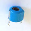
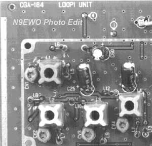
A nagging issue that has plagued the Japan Radio Co. NRD-545 over the years has been with the receiver going into a muted state. Either across it's entire range or just certain segments in the HF coverage of the receiver. In some cases when the CHE-199 option board is fitted it fails to operate too (mutes) making it appear that the converter board may be defective (which it still could be in addition to what is covered below ??). Serial numbers that are having this issue seem to be all over the place , right to the end of production in early 2008. It appears that it can happen to any sample that has ever been made ??. From reading the internet postings over the years on this bug, it appears that one POSSIBLE repair might be with one or more of the 4 plastic case "Murata" VCO trimmer capacitors on the CGA-184 Loop1 Unit that have gone sour ?? This would be CV1, CV2 , CV3 and CV4. Yes, this is just like with many ICOM models over the years that used the same lousy low grade Murata trimmer capacitors in the VCO circuits and elsewhere (models include : IC-745, IC-751 , IC-781, IC-R9000 , IC-970 , IC-275 , IC-475..etc). Sometimes one can rotate these trimmers slightly to make the set come back to life for awhile , but to only fail again later. Other times it's a total lost cause and all 4 should be replaced with a better grade trimmer capacitor. NOTE : The actual Murata trimmer capacitors that were used are no longer made (now discontinued thank goodness). The value is 2.7 to 10 pf . Alignment might be the tricky part of this POSSIBLE repair without the extension board that is almost impossible to obtain , the proper test equipment / service manual and of course the required skill to do it. I'm not saying this may be the "only" possible repair with any "muting issue" , however it may be a place to start ?? "Caveat Emptor" again for any NRD-545's in the used marketplace......Dave N9EWO IMPORTANT : I never had this bug happen to me and what information given here is for general reference only. Dave N9EWO © N9EWO, all rights reserved Ver 4.1
|
Dave's JRC NRD-545 Bandwidth Settings
(I changed
from "out of the box" settings, "What did Dave
use for his preset bandwidth settings ?")
|
kHz |
AM | SSB |
CW/RTTY
|
| WIDE | 9.90 | 4.00 | 2.40 |
| INTER | 8.00 | 3.00 | 1.00 |
| NARROW | 5.00 | 2.40 | 0.50 |
| # | JRC NRD-545 User Defined Functions | Values (MY Normal Settings in BOLD) (n9ewo chart) |
| 1. | 1 Hz tuning(SSB/CW/RTTY/AM frequency of less than 30 MHz) | 0: 1Hz not added to tuning step
OFF 1: 1Hz added to tuning step |
| 2. | 10kHz tuning(SSB/CW/RTTY/AM frequency of less than 30 MHz) | 0: 10kHz not added to tuning step 1: 10kHz added to tuning step |
| 3. | 1 kHz tuning(SSB/CW/RTTY/AM/FM frequency of less than 30 MHz) | 0:
1KHz 1: 5kHz 2: 6.25kHz 3: 9kHz tuning step |
| 4. | 100Hz tuning(FM mode/AM Frequency of more then 30MHz) | 0:
100Hz not added to tuning step 1: 100Hz added to tuning step |
| 5. | 5kHz tuning(Frequency of more then 30MHz) | 0:
5kHz 1: 6.25kHz 2: 9kHz tuning step |
| 6. | 10kHz tuning | 0:
10kHz 1: 12.5kHz 2: 20kHz 3: 25kHz 4: 30kHz 5: 50kHz tuning step |
| 7. | Tuning step automatic selection | 0:Automatic tuning step OFF 1:Automatic tuning step ON |
| 8. | Number of tuning knob pulses | 0: 1000 pulses/turn 1: 500 pulses/turn 2: 250 pulses/turn |
| 9. | Meter indication | 0: Single Display 1: Bar display 2: Peak Hold Display |
| 10. | Beep tone | 0: Beep OFF 1: Beep ON |
| 11. | Scan auto stop | 0: AUTO STOP OFF 1: AUTO STOP ON |
| 12. | Unwritten channel skip | 0: Skip OFF 1: Skip ON |
| 13. | Timer relay operation | 0:
Timer relay OFF 1: Timer relay always ON 2: Controled with Squelch |
| 14. | CW mode BFO offset frequency | -2550 to +2550(Hz) (10 hz steps) (0800) |
| 15. | RTTY baud rate (baud) | 37-75(baud) (45) |
| 16. | RTTY shift width | 0:
170Hz 1: 425Hz 2: 850Hz |
| 17. | RTTY polarity | 0: Reverse 1: Normal |
| 18. | SSB display frequency | 0: Display shift 1: Local shift |
| 19. | Display time colon blinking | 0: Colon blinking OFF 1: Colon blinking ON |
| 20. | Scan rate | 0.3-5.0(sec.)0.5 sec./CH (0.5) |
| 21. | Sweep rate | 0.05-0.5(sec.) 0.05sec./step (0.05) |
| 22. | Scan auto stop time setting | 0 to 10 seconds (0.5sec.steps) (3.0) |
| 23. | RTTY decoding output | 0:
Do not output 1: Output |
| 24. | Input tuning circuit | 0: Pass 1: Use |
| 25. | RTTY unshift ON space | 0: OFF 1: ON |
| 26. | RTTY error display | 0: Display space 1: * Display |
| 27. | Filter Hold of Noise Reduction (change in text from earlier manual--was called "Line Enhancer") |
0:
ON 1: OFF |
| 28. | Panel lock | 0: Lock tuning knob 1: All dials and buttons |
| 29. | Noise reduction next number change | 0.0000 (effect) to 0.0255 (No
effect) in 0.0001steps (0.0200) |
| 30. | Beat canceller next number change | 0.0000 (effect) to 0.0255 (No
effect) in 0.0001steps (0.0005) |
| 31. | Squelch LED lighting change | 0:
Lights when squelch is closed 1: Lights when squelch is open |
| 32. | Digital IF Filter setting slope | 0: DSP SHARP filter 1: DSP LOOSE filter |
|
FUNCTION
+ |
JRC
NRD-545 "Function" Button Operations (n9ewo chart) |
|
BWC |
Changes BWC Encoder Step (either 10 or 100 Hz) |
|
ATT |
Quick toggle of # 24 above "Input tuning
circuit", Useful when scanning memories..no relay chattering. (May not work on all samples, unknown ??) |
|
ENT/kHz |
Enter User Defined Functions (Above) |
|
CH |
Memory Channel Save |
|
FM/WFM |
Turn Stereo Mode ON/OFF (FM Wide Mode with CHE-199 Option Installed) |
|
CLOCK |
Set Sleep Time |
|
VFO |
Transfer Memory Information to VFO |
| PUSH
AND HOLD AT POWER UP (Power OFF and Repeat To Reverse Setting) |
JRC NRD-545
"Power Up" User Defined Functions (n9ewo chart) |
|
"." |
Unknown. The the display will
show a number like "12 46 13" (varies). Will not receive while in this mode. Just rotating the main tuning knob will restore the set to normal. |
|
ENT/kHz |
Toggles "Low End" Receive Range Down To 10 kHz. |
|
USB/LSB |
Allows USB/LSB and CW/RTTY Modes To Be Selected When CHE-199 Converter Is Installed. |
|
CLR |
Memory Channel RESET (WARNING:
Clears All Memories) and User Defined Functions To Default Settings. |
|
CLR |
Resets User Defined Functions To Defaults.(Keeps Memory Channels As They Were) |
|
CLOCK |
Toggles Seconds Display in Clock mode |
|
FUNC |
Display Test Mode, entire display lights up. Rotate tuning knob to restore to normal. |
|
Best "Free" Computer Software for
the JRC NRD-545
(link below is subject to change without notice) |
| There are a
number of "windows" based computer programs around for the JRC NRD-545.
This the BEST one I have used (in my view) and it's now freeware
. It requires a "Null Modem" cable or adapter between the receiver and
host computer (as all programs connected to the NRD-545 do). It does
not store the "tuning step" in the memory channels, so you will have to
do a touch up if you wish that (yes , the memories on NRD-545 you can
store the tuning step on each memory channel...this is neat indeed). The "NRD-545 Controller" program from Interfair Laboratory was written by H. Yamamoto in Japan. In was in Japanese only and also required registration with payment. Without it you could only start the program 30 times before it went bye-bye. The authors hard drive crashed and he has lost all source code for the program. Any additional improvements to the software are gone, so he decided to make it "freeware". J. Schimmele in Germany (with the OK from Mr. Yamamoto), has converted this program to English and is still "freeware". Again I feel it's the best out of lot tested and it allows for memory channels to be either uploaded or downloaded. Follow the instructions, you will have to type in the values shown in the registration as you bring it up for the first time. There is no installation garbage, it just runs in a directory that you place it in. Yes ran OK for me in Windows XP home and PRO, and even Windows 7 "32 or 64 bit" just fine. IMPORTANT NOTE : THE FUNCTIONALITY OF THE PROGRAM CANNOT BE CHANGED, USE IS "AS IS", AND AT YOUR OWN RISK !! NO WARRANTY OR SUPPORT, YOU ARE TOTALLY ON YOUR OWN ! PLEASE DO NOT ASK ME ! PLEASE NOTE : THIS SOFTWARE WILL NOT WORK ON "WINDOWS 8 , 10 or 11 (sorry) !! Download English Version "N545Pro" here, zipped size approx 400K (via radioscanner.ru web site) Dave N9EWO © N9EWO, all rights reserved Ver 3.2 |
The "Sherwood Engineering"
Roofing Filter
Modification
Via the newsgroups from Jim
Valle in regards to the Sherwood
Engineering roofing
filter modification (NRD-545). I'm actually totally against this
modification as it degrades AM audio in wider
bandwidths in my testing of a 3rd borrowed sample that had this
filter installed. Sorry ! N9EWO
"The 8kHz filter mod has really improved things for me
on MW and SW frequencies. Utility monitoring has been GREATLY
improved. I have found much less monkey chatter and significantly
less spillover from stations close by on all SW bands. The real
test is when I listen to utility and can get so much more out of
the passband tuning. A perfect example would be listening to AFN
in USB. Before the filter replacement there was quite a bit of
spill-over from data signals on LSB. This filter along with some
narrowing of the filter setting (about 2.2 to 2.4) and using the
passband tuning cleans audio up significantly. On MW I have found
no noticeable difference in fidelity. I live in an RF rich
environment and utilize the Dressler ARA-60 (superb antenna, by
the way) so I'm even more impressed by this filter mod. By the
way, you only need to send in the board, not the entire rig.
Saves on shipping. Bob turns things around very quickly. He is
also a very knowledgeable, professional and courteous individual
which to deal. All the best, Jim Valle "
Comment below was from when the NRD-545 first hit the market.
"Well..... I've
had one for about 4 months and I am rather disappointed with it.
In 40 years of SW I've never met a radio which runs out of AF
gain before,but this one does. The 'TONE' control has a very
peculiar action, at one end sound sounds like a telephone, at the
other treble boost. Receiving NAVTEX on 518 causes the AGC and BW
LEDS to flicker in sympathy to signal. VLF gain falls off rapidly
below about 70 kHz. At no settings can I get decent AM reception
with good signal. Awesome it aint."
Mike G3IJE
M.J.Powell.
(I will totally agree with Mike on the NRD-545 "running out of volume
control" . But only with under-modulated AM signals. The NRD-301
also suffers from this trait..N9EWO)
JRC NRD-545 Links (all subject to change without notice)
JRC NRD-545 eham ReviewsJRC Amateur and SWL gear (groups.io)