|
A few weeks ago I began to be concerned with frequency stability on one of my rig and I noticed that none of my small electronic lab equipment could be stable and accurate enough to make perfect or almost perfect adjustments. I investigated; looking for a simple and cheap solution to get an accurate time base or frequency standard.
I found several solutions.
1 – XO or cristal oscillator. Very cheap but very poor stability, accuracy and aging. Frequency stability about + 10 ppm. Not to be used in my case.
2 – TCXO or temperature compensated crystal oscillator. Much better characteristic and not too expensive, but not good enough. Frequency stability about +-1 ppm. Not to be used in my case.
3 – OCXO or oven controlled crystal oscillator. Again a step forward regarding all characteristic, higher price but still cheap to found on the net. Frequency stability about +- 0.01 ppm. This is the most common oscillator found in my lab equipment, but to adjust something like a OCXO you need something better by a factor of 10, 100 or even 1000. Not to be used in my case.
4 – RbXO or Rubidium crystal oscillator. Again better but begin to be really expensive and I found a quite too sensible device to be bought second hand on the net. I Read several times that this device doesn't like to be stopped and started again… Frequency stability about +- 0.001 ppm. Not to be used in my case.
5 – GPSDO or GPS disciplined oscillator. Again better but not too pricey and easily to found on the bay; very accurate in the long term. Frequency stability about +- 0.00001ppm.
6 – Caesium atomic frequency standard. A bit better but too expensive too big and need maintenance. Frequency stability about +- 0.000001ppm. Not to be used in my case.
7 – DCF77, MSF60 and others radio time standards are exclude due to short-term accuracy, very low noise immunity, limited range of reception and others negatives points.
The best choice for me is a GPSDO but which one. I found several HAM related models (at the time I write this article, they are all on the market) for a price tag between 200€ and 300€.
1 - http://www.ebay.at/usr/iw2nvw
2 - http://rudius.net/oz2m/ngnb/gps.htm
3 - http://www.jrmiller.demon.co.uk/projects/ministd/frqstd.htm
I choose the one from G3RUH, James R Miller, and although, I was (and I’m still) very happy with this item I was missing a clear and standalone 3D fix indication; the 3D fix inform that the oscillator is in the disciplined mode and that the precision is coming from the GPS and not that from the OCXO in the free run mode. As stated in the well done documentation, “if required The GPS receiver can be monitored via an RS-232 port” and it works perfectly (for free as there is some freeware for that), but your PC has to run for that and I don't want to be part of the 14 billion PC running for such a task or something unnecessary. The second way of knowing if there is a 3D fix is (again regarding the documentation) “to check if the 1 PPS LED is flashing exactly in time with MSF, DCF or WWV one second time marks”. Still too complicated and I would have to let one TRX running just to listen to DCF77, quite boring and energy consuming.
There must be another way to get this 3D fix visualization , and yes there’s always an HAM solution to a problem. This time the call of this HAM is W1AUV. The solutions W1AUV is offering is named 3DfixLED. A small solution using a PIC 16F688 and between 3 and 7 external components; depending of what you want as final result. I asked G3RUH if the 5 volt regulator will accept the extra mA (between 20ma and 40mA) needed by my circuitry and I got a rapid no probs response via e-mail (thanks James). My problem was, I had absolutely no idea about PIC, programmation and software to make all this magic happen. W1AUV is not offering (for a very small 3$) the programmed PIC anymore. I learned from a crash course on YouTube and ordered the necessary PicKit3, a solder less board to program and test the PIC16F688, some PIC16F688 (in case something turn bad, Murphy was an optimistic) and some veroboard. After some test I program with success my PIC and put it on the veroboard with 2 LEDs and resistor for integration in the GPSDO box.
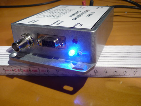
Bingo, it works perfectly. See the pictures to see how it works. No need any more of PC or radio running on the background to see if 3D fix take place.
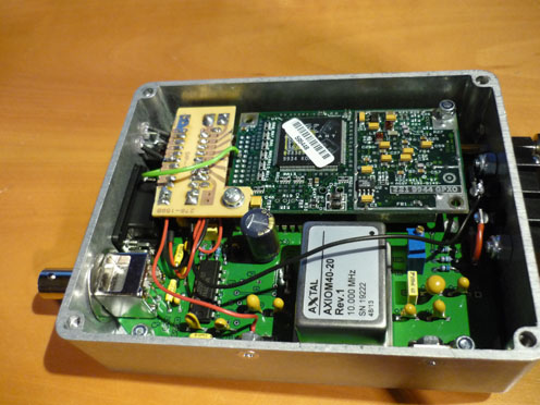 The first picture is the integration of the board containing all the component. The power is taken from the GPSDO 5Volt regulator, the ground is taken from the common ground. The PIC is working from 3.3Volt to 5Volt, thus perfect and easy. You can find the schematic here .The HEX file for the PIC is here and the source code is here. The first picture is the integration of the board containing all the component. The power is taken from the GPSDO 5Volt regulator, the ground is taken from the common ground. The PIC is working from 3.3Volt to 5Volt, thus perfect and easy. You can find the schematic here .The HEX file for the PIC is here and the source code is here.
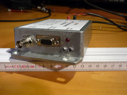
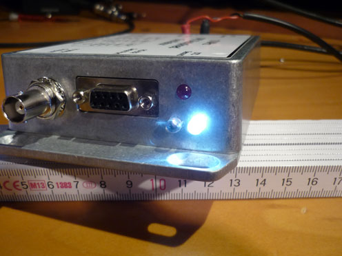
Two holes were drilled to the face to add the two LEDs.
The white LED on the right is signaling that good strings are received from GPS pin 11, the green wire on the pictures bring the string (4800bd, no parity, 8 databits and 1 stopbit). to the PIC, this LED must light a few minutes after a cold start from the GPS.
The added blue LED on the left must be lighting a few second after the white one and inform that a 3D fix take place, as long as the blue LED is on the white should be off.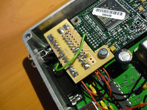
You can add a third LED if you want to signal that the PIC is receiving string that are not to decode, programation for this LED is already include in the HEX code but pay attention not to overload the PIC with high current LED, the rating for the PIC16F688 can be found here maximum combined current is 90mA (was before rated at 200mA, be warned). Useful informations like pin in pin and pin out about the GPS used in this system can be found here.
Next job is to add a power amplifier/ splitter for the 10 MHz output to be used on multiple device that need different voltage (even if it already works flawlessly, it could be neater with some insulation between all this devices). My PM6676 needs +6.98 to +40 dBm, my Marconi 2019A prefer to see +13 to +21 dBm and so on.
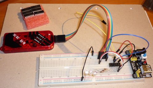 On the right picture you can see all the you need to program, test and run this project. On the right picture you can see all the you need to program, test and run this project.
1 PIC16F688 from microchip (Microchip is offering the software to program for free). You can find here some simple information on how to program this PIC.
3 220 ohms (depending on the LED you choose and how bright you want it to be. You can add just one, two or three LED.
3 LEDs again your choice.
1 PicKit 3 or Kit 3.5 depends on how genuine it must be.
A protoboard to program, test and run.
As usual enjoy and replicate.
|