|
As a family member, must have been the cat, lets fallen in the stairs my AOR LA320, nothing could have been done to rescue the long wave loop element which was plug in it at that time. From plastic to ferrite rod everything was destroyed. As usual and after a serious look everywhere, not a dealer had still in stock this sold out and outdated accessory. By the way, I don’t said before but this SWL indoor antenna is the very best I’ve ever owned and I own several others... Long wave, medium wave and tropical band reception compete really well with much much bigger antenna mounted outside. All others typical advantage from magnetic loop are present like interference nulling and much quieter reception as on vertical whip. You know that, I will try to make a new one by myself.
First I need a ferrite rod and sometimes ago I bough from Ukraine this ferrite rods. This one as an iniatial permeability of 400 (link to doc, sry in russian), a little to low for long wave use but I will survive with a smaller Q. For medium wave a permeability between 200 and 800 is ok and for long wave use an initial permeability from 500 to 2000 is wished. The rods I bough were made to suit medium wave receiver from the former Russia.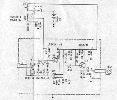
I need the schematic of the antenna, and thanks internet I got it. As you can see the antenna use 2 varicap from type KV1260 in parallel so we are now able to know the value from the capacitor in parallel with the coil we are about to make. Worst case will 61 to 890 pF and best case will be 45 to 1070 pF. Now using the freeware LCfreqs that you can find under the usefull tools in my LX2SM software page we can easily compute the value we need to match this varicap association. So I need a 2300 uH coil to make the antenna 45 to 1070 pF varicap resonant from 101 to 469 KHz.
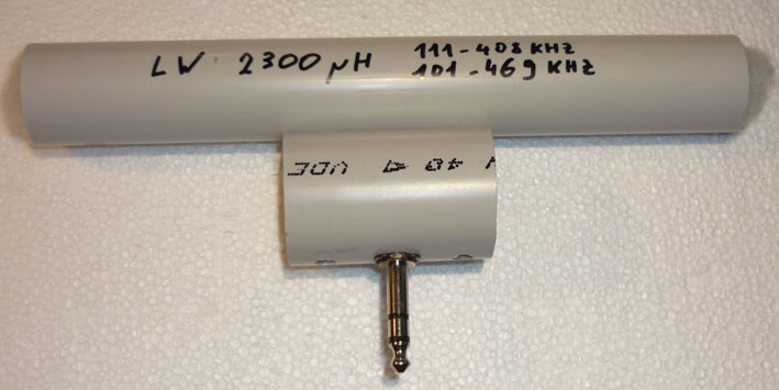
Next step is to compute the numbers of turns needed to make 2.3 mH with this rods or a combination of several of this rod. Having the permeability from the rod is a good thing but the Al value is more important. This time no information came from the web for this M400HH, ferrite type but M400HH is written M400NN in west Europe ( extremely important information thus completely useless for me). When I have an unknown ferrite rod, I usually used the proven ferrite toroid formula Al= 1000000*L/N² with good result, N is the number of turn, L is in mH. With 20 turns (at least 10 turns wound on the center of the rod) I found 51.31 uH 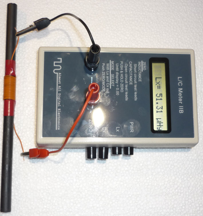 so I have an Al value of 128 lets take Al = 128. Turning the formula used before a little bit will give N=1000* √(L/Al), now I know the needed value 2.3 mH and I know the Al value 128 so for 2.3mH I would need 134 turns. You can see on the second picture (135 turns) give 2.4 mH so I have an Al value of 128 lets take Al = 128. Turning the formula used before a little bit will give N=1000* √(L/Al), now I know the needed value 2.3 mH and I know the Al value 128 so for 2.3mH I would need 134 turns. You can see on the second picture (135 turns) give 2.4 mH . If you wish you can combine several rods in parallel giving an higher Al value and less turns to wound. Several rods in //lel gives also more gain while several rods in line gives a better nulling. You can also see on the schematic that the original antenna loop make use of a center point, I read somewhere that this must give a better balance to the system and a better symmetry regarding interference nulling. I made 2 versions of my loop, 1 without center point (the prototype) and one with center point (final version), I really don’t see any difference so it’s up to you. The last picture is the final version with the connection fitted. . If you wish you can combine several rods in parallel giving an higher Al value and less turns to wound. Several rods in //lel gives also more gain while several rods in line gives a better nulling. You can also see on the schematic that the original antenna loop make use of a center point, I read somewhere that this must give a better balance to the system and a better symmetry regarding interference nulling. I made 2 versions of my loop, 1 without center point (the prototype) and one with center point (final version), I really don’t see any difference so it’s up to you. The last picture is the final version with the connection fitted.
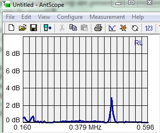
How does it works? Perfectly on the real world. You can see below a plot of return loss at 217 KHz, and another plot 458 KHz.
 As usual, enjoy and replicate. As usual, enjoy and replicate.
|