IN3OTD's web site
...under perpetual construction.

Dual-core power splitters
Here are some classic power splitter/combiner designs using two separate ferrite cores The typical design works quite well over the entire HF band and beyond and it can be further optimized to improve its performances at the lower end.
The splitter basic schematic:
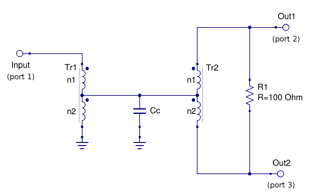
The Tr1 transformer is used to bring the 50 Ω input impedance down to the 25 Ω needed to feed the second transformer, Tr2. This latter is doing the actual power splitting feeding the two outputs. The resistor between the outputs is needed for isolation.
The circuit is quite simple but there are a couple of details that need some attention in order to obtain the best performances. One, well known, is that a compensation capacitance (Cc in the schematic above) is needed to obtain a good response at the higher frequencies, and its value depends on the transformer leakage inductance. Another detail, often not explicitly mentioned, is that the two transformers relative inductance influences the low frequency isolation flatness.
For all the circuits shown on this page the Tr1 autotransformer was made using a BN43-2402 binoculare core, with 5 turns (n2) from ground to the intermediate tap and 2 turns (n1) from the intermediate tap to the 50 Ω input, with 0.2 mm diameter magnet wire.
A good design
It has been observed in simulations that to obtain a good isolation between the outputs also at the lower frequency end the inductance of each winding of the output transformer (Tr2) should be the same as the inductance of the larger winding of the input transformer (Tr1). Since here the same type of core is used for both transformers this means in practice that the number of turns n1 and n2 of Tr2 must be the same as the number of turns n2 of Tr1.
The degradation of the low-frequency isolation when this is not the case will be shown below.
Note that the low-frequency return loss can be also improved, while keeping the a good isolation between the outputs, as shown in the optimized design below.
For this splitter, Tr2 was built on BN43-2402 binocular core with 5 + 5 turns of 0.25 mm diameter magnet wire.
With compensation capacitance
With the optimum compensation capacitance value (Cc=27 pF for this circuit) the high frequency response and return loss are good up to 100 MHz and beyond.
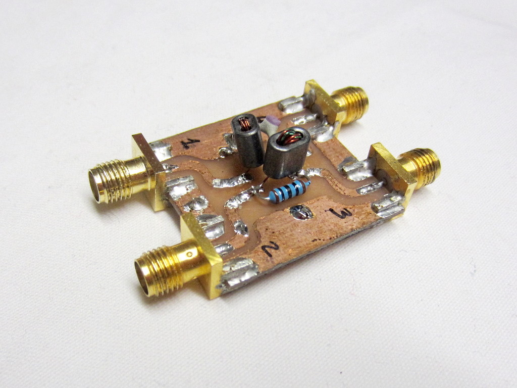
Here are the measured S-parameters for this splitter:
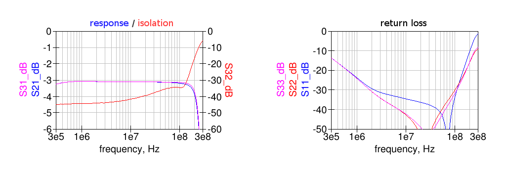
Note that the isolation between the outputs (S32) is flat and well above 40 dB also at low frequency.
The corresponding Touchstone file with the S-parameters data can be downloaded here.
Without compensation capacitance
When no compensation capacitance is used (Cc=0) the high-frequency response is limited by the transformers leakage.
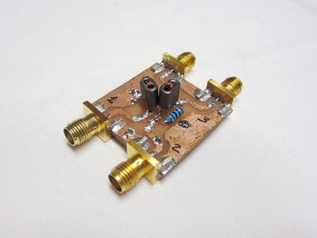
Here are the measured S-parameters for this splitter:
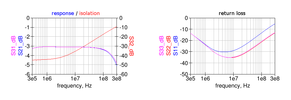
In this case all the parameters start to degrade above around 5 MHz.
The corresponding Touchstone file with the S-parameters data can be downloaded here.
Transformers relative inductance effect
The following measurements show the effect of different number of turns of Tr2 on the low-frequency isolation.
Tr2 having less inductance
For this splitter Tr2 was built on BN43-2402 binocular core with 4 + 4 turns of 0.25 mm diameter magnet wire, i.e. each one turn less than the n2 winding of Tr1.
With compensation capacitance
Here the same compensation capacitance of 27 pF as above is used.
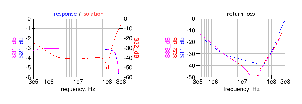
In this case the outputs isolation gets worse at lower frequency, due to the different magnetizing inductance of Tr2 compared to the n2 winding of Tr1.
Here are the measured S-parameters for this splitter.
Without compensation capacitance
For completeness here are the measured performance with Cc = 0.
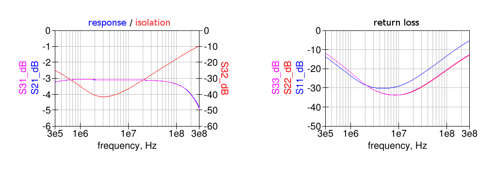
Of course the low-frequency response does not change, only the high-frequency end becomes worse.
Here are the measured S-parameters for this splitter.
Tr2 having more inductance
For this splitter Tr2 was built on BN43-2402 binocular core with 6 + 6 turns of 0.25 mm diameter magnet wire, i.e. each one turn more than the n2 winding of Tr1.

With compensation capacitance
Here the same compensation capacitance of 27 pF as above is used.
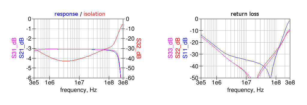
In this case the outputs isolation gets worse at lower frequency. This is due to the different magnetizing inductance of Tr2 compared to the n2 winding of Tr1.
Intuitively one would think that more turns on Tr2 would improve the low-frequency performance but this is not the case for the outputs isolation, which depends also on the actual impedance driving Tr2.
Here are the measured S-parameters for this splitter.
Without compensation capacitance
For completeness here are the measured performance with Cc = 0.
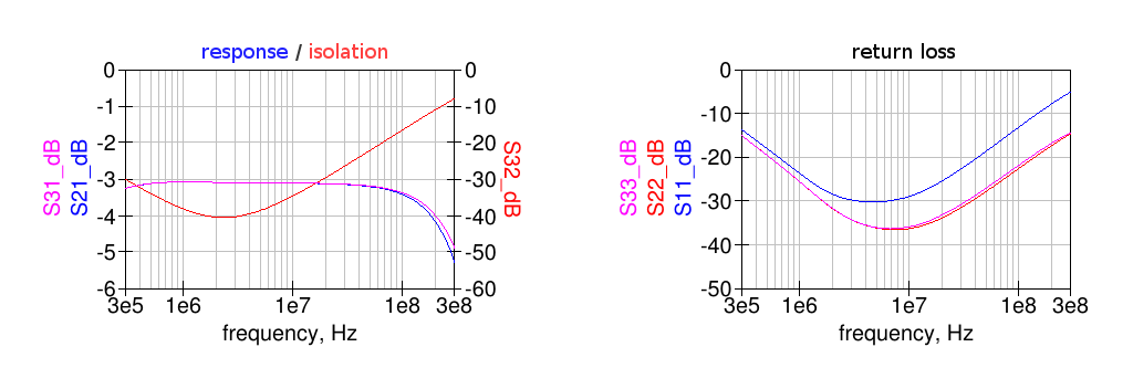
As expected the compensation capacitance had an effect only at high frequency.
Here are the measured S-parameters for this splitter.
An optimized design
The splitter design described above has a flat isolation between the outputs at the low-frequency end, when properly designed, but its return loss at all ports increases due to the finite magnetizing inductance of the transformers.
To extend the low-frequency response a higher number of turns could be used, in order to obtain more inductance but this will compromise the high-frequency end due to the additional inter-winding capacitance and increased leakage inductance.
A better way to improve the splitter behaviour at low frequency is to add series capacitors to the ports; together with the leakage inductances this will give a second-order highpass response instead of first-order.
To maintain the splitter symmetry, the capacitors should be added to the output ports only.
Here the simulated coupler response (with Cc=27 pF) when 27 nF capacitors are added in series to the output ports:
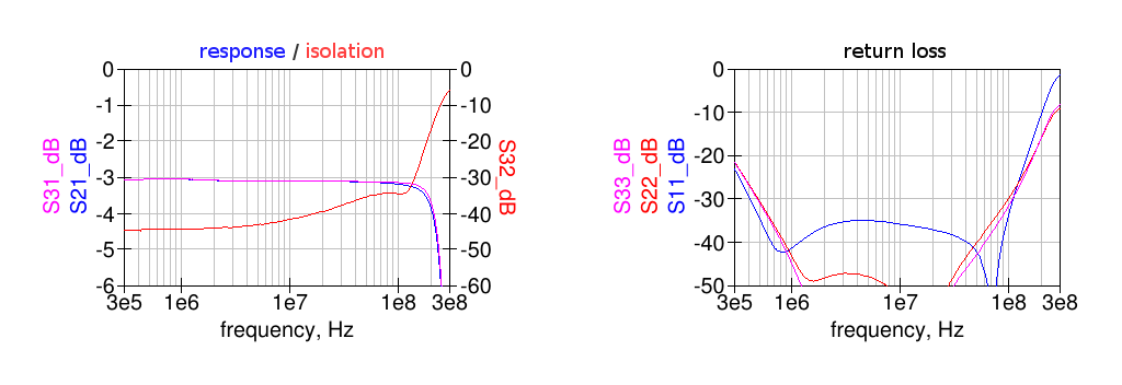
Compared to the response without series capacitors above this design has a much flatter response and return loss on all ports.