Testing - 3rd Session
Further testing was carried out. Much more work was done on the spreadsheets, so that as well as following the method in the manual there is a "check back" feature, calculating the expected frequency from first principles. fo = fin (m*n + a)
This all seemed to line up correctly.
So, I could not really find any explanation for the issue (other than mixing up "A" and "B" data bytes initially), but I went through it all again, to check. As before, the Rx was working on one channel only, but 500kHz out.
Back to inspecting the two radios, and a difference was found on the RX PCB's
It would appear that he 1st IF frequency is *not* 21.6Mhz on the radio we were been working on (NJ8812) its actually 21.4Mhz.
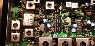
The two photos show the markings on the IF crystal filters:
Radio 1: ["IAN" NJ8812 PLL] 21.4 MHz Filter 2nd IF crystal 20.945MHz
Radio 2: ["ROBIN" MC145146 PLL ] 21.4 MHz Filter 2nd IF crystal 20.945MHz

Success at last.
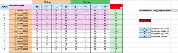
We re-calculated all the necessary bytes for 16 simplex channels using an IF of
21.4MHz, reprogrammed to Eeprom.
Radio now receives signals from both Quansheng and Icom 2m handsets, at the
correct frequencies.
Chart shows the necessary bytes I used
Well inspired by my success with the "Ian" radio, we Tried to adjust the second Zycomm "Robin" radio. This was pushing our luck, I know, and sure enough it was having none of it.
As found, it operates around 77MHz. So we tried 100Mhz as an incremental adjustment, (moving towards 144Mhz) but nada. VCO so far out of range it won't pull back into lock when you adjust the Inductor.
Oh well, might need to change some capacitors on the VCO board.
Checked with the guys on the Vintage radio forum for Any
ideas.
They advised that this change would not work without some substantial RF redesign. Not only will the VCO be unlikely to track that far but, the RF circuits won't adjust that far either. As the radio was designed for VHF low band, probably with an overall design range of 68-88Mhz and trying to stretch it anywhere too far outside of those boundaries will require RF re- design.
They suggested we programme the low band [“Robin”] radio for the 16 FM simplex channels on the 4m band as it makes much better sense to move the radio to the amateur band nearest to the radio's original operating frequency.
We a review today of our progress so far, and also revisited
the radios and their documentation, to explore where we would end up, should we
start changing the VCO and trying to progress from there.
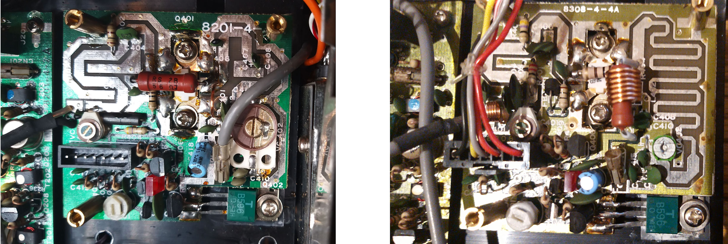
We deduced that should the task resolve into just swapping capacitors here and
there - then it might be possible -- but the first big stumbling block looks
like the "TX Driver and APC Board" which has got some kind of
inductors (transmission lines ?) built into the PCB. (See photos below).
So, in conclusion, taking the advice given, and our own
inspection of the Radios , we decided that trying to get the Low-Band radio
converted up to 144Mhz is a non-starter.