Phase Locked Loop
Understanding the functionality of the Phase Lock Loop frequency synthesiser is key to re-adjusting these radios. I am indebted to the guys on the UK Vintage Radio Repair and Restoration Forum for guiding me through this process.More...
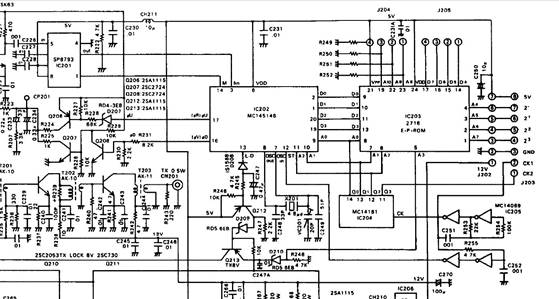
The manual extract (below) details how to determine the content of the Eprom bytes. We can ignore the CTCSS side of things, as there is a 3rd party board fitted for that function.
The bytes are constantly written into the PLL chip by a simple CMOS oscillator circulating around the first three bits. Meaning that there are 8 bytes per Tx or Rx setting
From the schematic we are expecting that the state of A3 will change when the set goes from RX to TX and back - and (although we don't have that confirmed practically yet) from the manual it looks like A3 is high on Tx (Not Rx)
Since A3 does follow the PTT state then the characters in the EPROM are likely to look like this:
Bytes 0 to 7 Channel 1 RX frequency (only lower nibble used)
Bytes 8 to 15 Channel 1 TX frequency (only lower nibble used)
Bytes 16 to 23 Channel 2 RX frequency (only lower nibble used)
Bytes 24 to 31 Channel 2 TX (frequency (only lower nibble used)
...and so on all the way up to channel 16 - assuming 16 channels because the code applied by the channel switch to the EPROM A4-A7 is 4-bit.
(NB Careful not to get confused here between 3 bit address and 4 bit data
As suggested, I focussed on one group of 8 bytes. As described in the manual for each byte only one nibble is used - as the PLL only has a four-bit data bus. Also, as seen in the manual’s example, the upper nibble has all bits set to “1”s – ie “F”. So this should result in Eprom bytes containing values such as F0, FC etc
Initially, I worked though the example calculation methodology from the manual, by means of a spreadsheet. So far – so good. I think my understanding of it checks out

I then built an Arduino Based Eprom reader based on work done by a Youtuber called Ben Eater
https://www.youtube.com/watch?v=K88pgWhEb1M&t=1954s
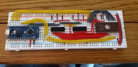
After building de-bugging and learning a bit about Arduino dialect C++ I managed to extract the settings from our Eprom

The first thing to note here is that for each byte the upper nibble (unused by the PLL) has all bits set to “0”s – ie “0”. resulting in the Eprom bytes containing values such as 00, 0C etc
Finally, I expanded my spreadsheet idea - so that it works in reverse – so that I could enter the bytes that I read from the Eprom and back calculate what the TX and Rx frequencies would be Unfortunately - the results were rubbish and the calculations came out with wildly different Tx Rx frequency- so I now need to double check everything and try another Eprom.
Other notes:
The PLL reference frequency is 4.8MHz.
1st IF is 21.6Mhz, second IF is 455kHz.
1st local oscillator is derived from the PLL,
2nd local oscillator is a 21.145MHz crystal.