Display & Control Board
This section descibes investigations into Display and control board.
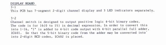
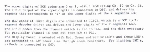
1. “Zycomm” Manual
First – this except from the “Zycomm” Manual

Tried to run a simulation in Multisim, but found that the 74185 is an obsolete device, so couldn’t do the simulation. In fact not made for many years.
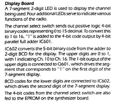
2. Looking at the Neutec Manual
From the Neutec Manual

The 74185 has basically been replaced with an odd diode “AND/OR” circuit (although strangely it still lives on in the block diagram in the manual).
This newer Neutec circuit can be modelled and tested in Multisim
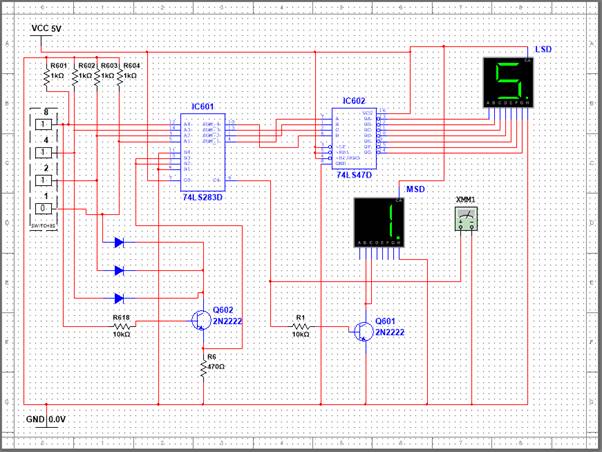
The binary is taken and basically bumped up to two digits of BCD, albeit thet the left digit is “1” or off.
The binary has one added to it all the time as the Carry in terminal is wired to Vcc.
If the “8” bit comes on then Q602 is switched on. Then if any of the other bits 0,1,2 are on the collector sees Vcc through the diode and 3.5V appears across he emitter resistor, adding another 6 to the count.
3. LAYOUT
Here is the PCB layout from the Neutec manual
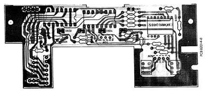
This is also wrong in terms of the shape and topology.
Here’s the real one:
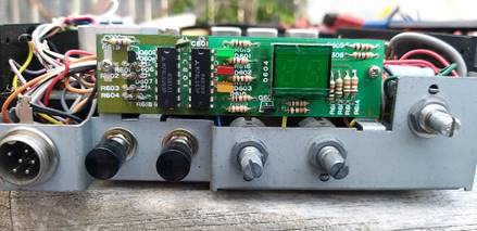
The circuit schematic looks correct based the on a visual inspection but the physical topology is different