Introduction
End fed wire antennas have been around since the early days of radio, recently half wave end fed wires with a 49:1 matching transformer have become fashionable, as has using an ATU to create a low SWR at the transmitter.
Typical end fed wire installations are mostly horizontal, which is fine for contacts out to around 500 miles with sky wave, but they are not optimum for DX.
An easy option for those of us with relatively small gardens it to use a fiberglass pole to support a vertical wire, a quarter wave vertical for 40m is roughly 32 foot 6 inches with PVC insulated wire. When used with a reasonable number of shallow buried radials, it will work well for DX on the 40m band. Unfortunately, a ground mounted quarter wave vertical for the 20 to 10 metre bands has a less competitive performance relative to other stations, even though a good SWR is easily obtained.
Using a 49:1 transformer does allow a half wave vertical to be matched, for example a quarter wave 40m vertical wire is a half wave on 20m and a full wave on 10m. Unfortunately, the base loading effect of the 49:1 transformer results in needing to shorten the wire for optimum matching on those higher bands and that creates an unacceptable SWR on 40m when used as a 40m quarter wave.
Another option could be to use a remote ATU at the base of the vertical. The limitations are twofold, most will not match a half wave wire and few are rated more than 100 Watts. While a simple L-Match is only a single band solution, it is easy to make one that handles high power levels and will match a very high impedance. Radiation pattern
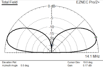
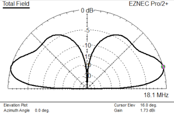
On 7.1, 10.1, 14.1 and 18.1 MHz, a ground mounted vertical wire around 32' 6” long will have a low angle of radiation on the higher bands and around 26 degrees on 40m The low angles of radiation on 20 and 17 are particularly useful for DX.
Feeding the vertical
The source impedance of our vertical wire is in theory around 2450 Ohms on 20m, which sounds ideal for a 49:1 transformer, but as it also introduces base loading, it's not so good. Martin, K1FQL, produced an excellent paper on building single band L-Matching units to feed a half wave antenna (link at bottom of page). I will not go over the same ground as Martin as his paper covers the issues well. Courtesy of an “on-line” calculator, it is relatively easy to compute the values of inductance and capacitance to match the same wire on higher frequencies.
Obtaining the figures to enter into an on-line calculator
The images below give a confusing result, these were obtained by connecting the output the AA230 directly to a 32 foot 6 inch vertical wire fed against ground.
This is the same wire, using a NanoVNA H4 to measure it. Note the similar R and j measurement to that obtained with the AA-230 in series mode.

Using the same wire, this time using EZNEC, the results are quite different.
EZNEC SOURCE DATA
Frequency = 18.1 MHz
Impedance = 106.8 - J 451.2 ohms
For my purposes, I am inclined to use the EZNEC data, even though it is theoretical.
Calculating the values for an L-Match
Fortunately, this doesn't require a spreadsheet or your calculator, as Analog Devices have a free one available (link at bottom of the page). Take the EZNEC impedance figures and enter the following into the Analog Devices web page calculator.
Frequency 18.1 MHz, Source 50 Ohms (0j), Output 106.8 Ohms (-451.2j)
The result is shown in the first diagram and copied below. The calculated L-Match values are:
L1 = 2.755 uH and C1 = 8.916 pF

The AA230 and NanoVNA produced significantly different results to those from EZNEC. On 18.1 MHz the EZNEC figures produced a working L-Match, the results shown in the images below speak for themselves. Maybe I should have tried a 29 pF or 35 pF capacitor, as suggest by the AA230 and NanoVNA?
Construction and measured results
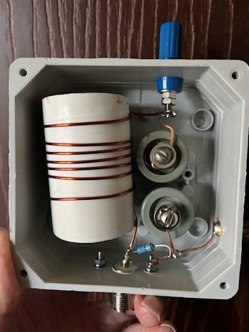
The image of a 20m L-Match shown at the top of the page shows the typical construction of a single band L-Match built in a Geros GR17004 case, these are 100 x 100 x 60mm and IP65 rated. Drill a small vent hole in each lower corner, seal the inside of the sockets and ground screw with 704 silicon sealant. The inductor is wound on a piece of 40mm diameter plastic tube.
The static drain resistor is a 1/2 Watt high Voltage type. Any value of a few K Ohms upwards will be fine, obviously not needed if you opt for the serial capacitor and shunt inductor configuration.
For the 18.1 MHz example, wind 7 turns of 16g enameled copper wire on a 40mm diameter former (in the UK we use that size for kitchen and bathroom waste water pipe), wire a 15pF and a 22pF cap in series (or a single 9pF), plus a static drain resistor across the input and you are QRV.
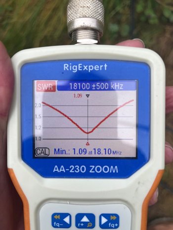
The calculated values are by no means guaranteed, some stretching and squeezing of the coil will be needed, once a satisfactory match is obtained, secure the coil with a couple of blobs of hot melt glue. The resultant SWR plot close to the L-Match on 18.1 MHz is excellent, see below.
The capacitors are surplus "door knob" types from Eastern Europe, with a specification of 8 Amps and 10 KV. Sadly the supply of these capacitors has more or less dried up in recent times. You could use a piece of RG400 PTFE coax as a capacitor, it is 94pF per metre (96mm is about 9pF).
Other band combinations
A 1/4 wave vertical for 30m is also a 5/8th wave on 12m. Pick the wire length and see what the pattern looks like with EZNEC, you should be able to match to 50 Ohms with an L-Match. I am currently using the 1/4 wave 40m wire on 40m and 15m (direct feed via a common mode choke), and on 30m and 17m with L-Match units.
Power rating
Using the above surplus capacitors with my 500 Watt linear has not caused any issues. Using the same capacitors at higher power levels should be OK, they have been previously tested at 1 KW in the trap on a dual band vertical. RG400 coax seems OK when used as a capacitor at 500 Watts, but it is not rated to the same high Voltage as surplus door knob capacitors, in any event if using coax as a capacitor, trim back the braid at the open end and cover the end with hot melt glue.
Conclusion
Whether the antenna analysers, or EZNEC, produce the better result is hard to determine as in theory an antenna analyser should give measurements well away from the usual 50 Ohm impedance. I take the AA230 and NanoVNA values with a large pinch of salt and use the EZNEC values. What certainly would work is a temporarily constructed L-Match using a variable capacitor and a coil of your choice, adjust them for a good match, then measure the values with an LCR meter and make your QRO L-Match based on those values.
Links
Analog Devices L-Network Calc
Original L-Match article by Martin K1FQL
EZNEC


|