Matt Meola
ex KCØDXW
|
Matt Meola ex KCØDXW |
|
|
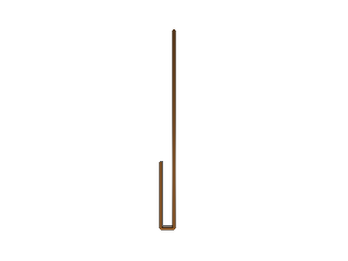
The Ubiquitous J-PoleA J-pole antenna is a common sight among those who work the VHF and UHF bands; they're easy to build and they perform well. My first experience with a J-pole came shortly after getting my Technician license, and a copy of the Amateur Radio Handbook. In there, were plans for a j-pole antenna, and one that could be pretty easily made from copper pipe, as commonly found in the hardware store. I was intrigued, so I went off to my local store and built one. At that time, my only radio was an Icom W32A handheld, so a j-pole mounted above my back deck was a tremendous improvement. Since then, I've built a "Super J-pole", plans for which are found in the ARRL Antenna Book; and a "Mirrored J-pole", which can be found here. It is interesting to note that a j-pole is a half-wave radiator with a quarter-wave tuning stub made from, essentially, a parallel wire transmission line. Since that quarter-wave stub is rigid, it does not need any other support, but it is pretty much the same thing as ladder line. My modeling of j-poles indicates that the stub seems to provide a fair modification of the normal, circular pattern. It seems to actually flatten the other side; in the pattern below, the quarter-wave stub is on the top side. If you click on the "Larger Version" link in the caption, you'll see that there's almost a 3db F/B ratio. Also note that, compared to a typical half-wave dipole, the J will have more gain, at least in the direction of that stub. That's probably an effect of having 50% more metal in the air -- it has a larger aperture, so it will both radiate and intercept more energy. 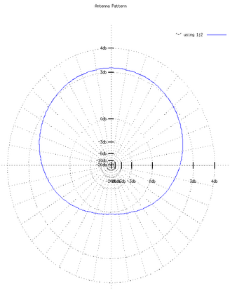
ERP Plot (Larger Version) Many people say that a half-wave antenna "doesn't need a ground plane". That's one of the reasons why many people favor j-poles. They are mistaken. Every end-fed antenna needs some kind of counterpoise, otherwise there will be currents flowing on the transmission line; in most hams' case, that'll be common-mode currents on the shield of the coax. Either feed your j-pole with a balun (which can be made by coiling the coax at the feed point) or provide a ground plane. Shown below are two plots (ERP and ARRL) of all three of the j-pole type antennas. The blue is a standard j-pole, the green is a super-j, and the red is a mirrored-j. It is interesting to note that it is the super-j that has the most circular pattern. 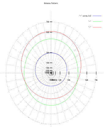
Combined ERP Plot (Larger Version) 
Combined ARRL Plot (Larger Version) |