At it's simplest, a radio comprises little more than a mixer and oscillator giving an audio output when the signal and oscillator are within a few KHz of each other. Direct conversion receivers are an example of this simple type of receiver. If the audio output is fed to a sound card instead of an audio amplifier, the results can be displayed on screen using one of the free audio spectrum analyser programs. The performance is limited by the purity of the oscillator and the dynamic range of the PC sound card, however for something that costs around the same price as a magazine and an hour or so of your time, you can have a working spectrum analyser with an amazing specification - by using a 24 bit sound card you can have a noise floor of -140 dBm, dynamic range approaching 140 dB (that is a bit tongue in cheek as that's theory... not necessarily more than 100 dB in practice), a bandwidth of less than 1 Hz and a frequency range only limited by your mixer and oscillator. This approach won't enable you to check for harmonics and wide spaced spurious signals, but it is an easy and cheap way to check "in band" IMD such as 3rd and 5th order IMD in SSB transmitters and for key clicks in CW transmitters. You may also be able to set the deviation of FM transmitters.
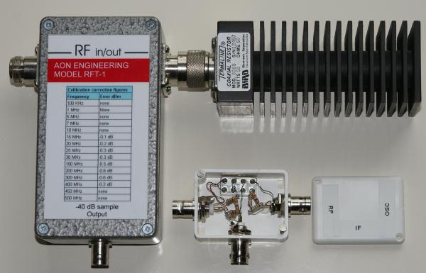
The parts required to build a simple spectrum analyser are shown above, the die cast box contains a -40 dB resistive tap built from the article in June 2001 QST called "Simple RF Power Measurement" by Wes Hayward and available from the ARRL members section of their web site. The resistive tap takes a sample from a coaxial line and is broad band from DC to at least 500 MHz. The Bird dummy load shown is attached to one side of the tap, a transmitter connects to the other N socket. Below right is an SBL-1 diode ring mixer with 6 dB attenuators on the IF and oscillator ports. A 6 dB pi attenuator comprises a 39 Ohm resistor in series and a 150 Ohm resistor to ground each side of the 39 Ohm resistor. The RF port connects to the -40 dB output of the resistive tap, a signal generator with a signal level around +10 to +13 dBm feeds the attenuator on the oscillator port. The IF port connects to your PC sound card. The signal generator should be set to 5 KHz or so below the transmitter frequency.
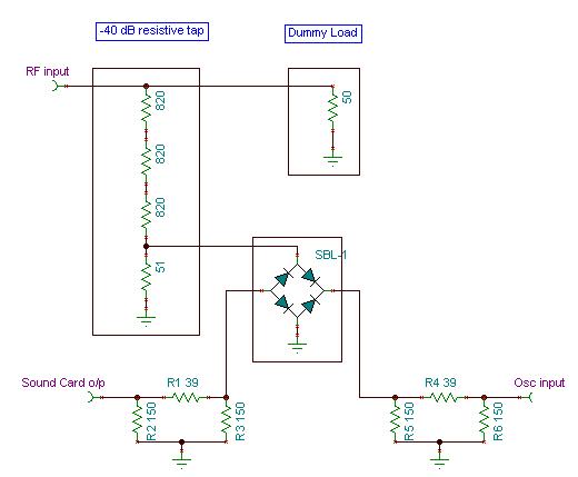
The diagram below illustrates how the modules are used. The attenuator feeding the sound card seems to work the same as putting a 56 Ohm resistor directly across the SBL-1 IF output. Whatever you do, don't directly feed the mixer to your sound card as it will be badly terminated and generate intermodulation products. Equally, if your signal generator has a true 50 Ohm output impedance (and most do), you can leave out the - 6dB attenuator on the oscillator side, which would result in needing an oscillator feed directly to the SBL-1 of +7dBm. The SBL-1 is shown as a simple diode ring, as that was all that I could find in my schematic drawing package. A variable attenuator between the resistive tap and the SBL-1should be used to minimise overload when testing transmitters with power levels in excess of a Watt or two.
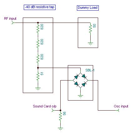
For a minimalistic version, which provided you are using a professional grade signal generator with a 50 Ohm output, this is all you need. The differences between the two are virtually non existant. Terminating the sound card output in a 56 Ohm resistor seems to work perfectly well too.
My current favourite program for audio spectrum analysis is "Spectrum Laboratory" by DL4YHF and available for free from:
http://www.qsl.net/dl4yhf/
The program is fairly easy to use, although it takes a little getting used to. There is a two tone oscillator within the program which is handy for SSB transmitter testing. An example of the results of a two tone test on an Icom IC910HX on 70cms and the bandwidth taken up by keying an Elecraft K3 at 20 words per minutes are shown below.


|
