
Note: synth kits from both Cumbria Designs and SDR Kits are no longer available.
Background and design
Going back a few years, to at least the early 1970s, using separate transmitters and receivers was a fairly common practice among radio amateurs. By building "separates" you are duplicating some circuitry compared to a transceiver but it does give great flexibility. This receiver was originally built to replace a Drake R4A which had been used in conjunction with a simple crystal controlled transmitter. This receiver outperforms the old Drake by a significant margin and yet is fairly straightforward to build using off the shelf parts, modules and case. The details presented here are intended to assist others with previous building experience to construct a similar receiver, rather than being a step by step guide. Also being modular means parts of the receiver can be utilised in your own projects. Feel free to browse and copy!
While I have used several SMD boards, through hole parts could equally be used to build the IF and other boards. SMD parts have the advantage of often being cheaper than through hole and in reality are often easier to work with than through hole, if for no other reason there is no need to drill so many holes in the boards.
An IF frequency of 8.215 MHz was chosen based on having a pair of suitable filters and also a selection of crystals for that frequency. 8.215 MHz will mix with the minimum frequency of the synthesiser (10 MHz) to cover from 1.8 MHz upwards. "High side" oscillator injection is used on all bands. Although I have based my band pass filters on the 10 HF amateur bands, reception is possible anywhere on HF with suitable band pass filters, the exception being a small block around the IF frequency. Any IF filters in the 8 to 10.7 MHz range are are suitable for use in this receiver. The filters I used came from a Yaesu FT757 and use a rather odd centre frequency for the CW filter (8.2159) which means it can use the same BFO crystal for USB and CW, although the SSB filter is centred on 8.215. The choice of filters will need to be considered in conjunction with whatever IF offset your synthesiser or display can accommodate.
The performance is more than adequate with a two tone dynamic range of 94 dB at 2 KHz signal spacing, and an IF rejection of at least 80 dB (87 dB IF rejection measured on 7 MHz, possibly the worst band). The image rejection is at least 70 dB improving to better than 100 dB on 1.8 MHz. Only the top few amateur transceivers can better the dynamic range performance of this design. These figures could be improved at the expense of more complex band pass filtering and by using a stronger mixer with a higher level of oscillator injection. The minimum discernable signal (MDS) is -127 dBm (0.1 uV) on all bands without the pre-amp, and a few dB better with the pre-amp. Frequency stability is excellent. In my shack, with a stable ambient temperature, measuring against the 29 MHz harmonic of a GPS locked frequency standard there was less than 20 Hz drift during the first hour after a couple of minutes warm up, followed by less than 2 Hz drift over the next hour.
At the heart of the receiver are two modules that make assembly fairly straightforward. The IF and AGC board is the "Hybrid Cascode IF Amplifier" by Wes Hayward (W7ZOI) and Jeff Damm (WA7MLH) from the December 2007 edition of QST. Members of the ARRL can download the original article from their web site, non members can visit W7ZOI's web site for circuit details. The IF/AGC works exceptionally well and saves a lot of hard work sourcing odd parts as it comprises easily found generic components.
The second module is an Si570 based synthesiser by Cumbria Designs used with their mini counter frequency display. The synthesiser is capable of generating an output of 10 MHz to 250 MHz at a level of +10 dBm, although in this receiver the frequency is set for an upper limit of 38.215 MHz (corresponding to a receive range of 1.8 to 30 MHz). The mini counter caters for up to 6 user chosen offsets from a centre frequency and means that almost any filter and BFO frequency can be used with it. Unfortunately, checking with Cumbria in December 2013, they have been out of stock of these items for some weeks with a possibility of no longer supplying them. However, the design can utilise synthesisers from other suppliers, such as those by SDR-Kits (http://www.sdr-kits.net/) some of which cater for SSB/CW offset (although they may not be offsets that you can adjust), have RS232 capabilities and that can also switch band pass filters.
The receiver synthesiser drives a buffer/splitter which provides an output to transceive with my Companion or SSB Transmitter. If built to operate either stand alone, or with a different transmitter, this buffer may not be needed.
I etched one board for through hole parts and five for SMD parts, the IF filter board (through hole) and for SMD the synthesiser buffer/splitter, Hycas IF, S-meter, BFO/product detector and the AF pre-amp/filter. The other boards were made using a series of "islands" or "pads" created with a 7mm diamond tipped tubular "drill" of the type used to drill ceramic tiles (mount your drill in a stand to avoid it wandering all over the board). The audio amplifier is a Velleman K4001 kit.
The case used is a "Unicase 2" by Metcase (www.metcase.com), part number M5502119, which measures 260 x 90 x 250mm (W, H, Depth). These cases are stocked in the UK by RS Components (769-4908). An aluminium sheet is fitted in the centre of the case which is not supplied with the case. The knobs, including a 31.8mm diameter tuning knob, are from eBay suppliers. The S-meter is a surplus 250uA FSD one from a Yaesu FRG7000 receiver, with illumination by a white LED. An alternative meter is the signal meter from Maplin.
As an absolute minimum the BFO needs to be enclosed in a screened box, this can be made from scraps of print board. The IF and filter boards are very sensitive to stray signals and should be enclosed too. In a case of "do as I say", rather than "do as I do", adding screening to the band pass filter board and synthesiser is a good idea. The BFO and synth each produce around 10 mW of signal and that is strong enough to radiate several miles on an antenna. On 160m the synth operates close to the IF frequency and can desense the receiver if there isn't sufficient screening.
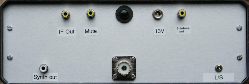
The front panel was produced in Corel Draw and printed on photo card, which in turn was glued to the aluminium panel with photo mount spray adhesive. A clear plastic self adhesive "book protector" film was stuck over the card to protect it.
For a view of the underside of the receiver click here, for an upperside view click here.
Module and circuit details
Below are diagrams in PDF format:
For a set of board layouts for the SMD versions of the synthesiser buffer/splitter, Hycas IF board, S-Meter board, BFO and AF filter board, in Sprint-Layout 6 format, and an encoder interface board layout, click here for the Zip file. There is a link at the bottom of the page for a free viewer program which can be used to print these layouts.
Band Pass Filters
There are 10 band pass filter boards selected by a 1 pole 12 way front panel switch, these are relay switched to minimise IMD. Each board is constructed on single sided PCB (avoids possible shorts to adjacent board), and individually tested/aligned before being added to the main board. The filter design was done using the freeware Windows program "Elsie", using a topology of "Mesh Capacitor-coupled band pass" and "Chebyshev" Family of 3rd order (uses 3 inductors and 5 capacitors per filter, actually produces "5th order filter"). The design was altered to use the nearest 5% capacitor value with inductors wound for the required inductance using a low cost L/C meter. For those not familiar with this program, beware of the default Q settings of capacitors and inductors being excessive (a value of 200 ~ 500 is more realistic) and also set the transmission to "Absolute", both these settings are found under the "Analysis" tab.

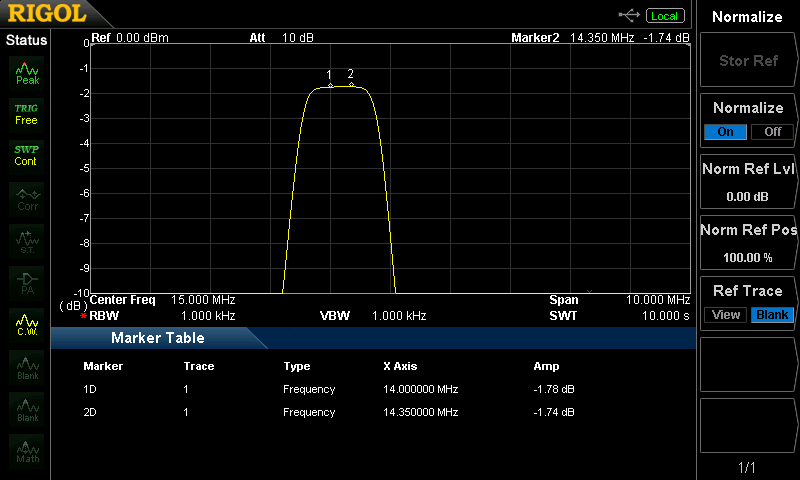
Capacitor and inductor values are critical, being off by a few percent can make a huge difference to performance. Unless you can source close tolerance capacitors, you will generally have to make up the required values by connecting 2 or 3 in parallel and measuring the value with an LC meter. The toroids should be wound for an extra turn and then fine adjusted by removing a turn or two and/or moving the wires on the core until you obtain the required value, estimating the value based on the number of turns may not produce good results. The ideal way to measure the inductance is to check the resonant frequency with a known value capacitor in parallel using a dip meter. Unfortunately, many of the LC meters use a 500 KHz oscillator and this can lead to problems with coils wound on iron dust cores, such as the ones used in these band pass filters. For the higher bands, trimmers were used for the series capacitors (7 MHz and above). T50-2 cores were used from 1.8 to 10 MHz with T50-6 on the higher bands. Ideally, use silver mica or polystyrene capacitors for higher Q and less filter loss. Measured loss with ceramic capacitors in a 14 MHz band pass filter was 3 dB, the same filter with silver mica capacitors was just under 2 dB (image below).
The frequency response graphs produced by the Elsie program were pretty close to my measured results. See circuit diagram for my calculated values, however, the Elsie program is so easy to use that you can produce your own values easily enough. Do not try to cover too wide a bandwidth when designing the filters, as the image and IF rejection levels are better for narrower bandwidth filters. However, if you attempt to make too narrow a filter, you will find it gives excessive loss. Typical measured loss figures for these filters vary from less than 1 dB to 2.5 dB when measured directly between the input inductor and output capacitor on the board (ie without the relays). There is a series tuned circuit across the output of the band pass filter rail to ground which notches out the IF frequency, I used a 12 uH coil wound on a T37-6 toroid with a 65 pF trimmer capacitor.
Each band pass filter is "tack" soldered to a mother board, with the relay switched input/output soldered to a common bus bar.
Other bands could easily be accommodated as the filters are switched independently of the synthesiser, the only limitation being that you cannot receive near the IF frequency. Using this arrangement of filters, synthesiser and separate counter will allow operation to 50 MHz with appropriate filters. The synthesiser itself is capable of operation to more than 200 MHz.
Synthesiser buffer amplifier/splitter
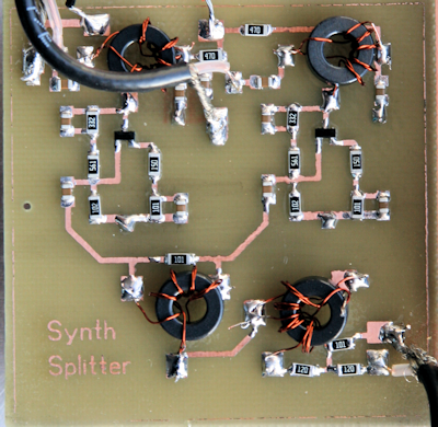
This optional board splits the nominal +10 dBm synthesiser output to provide a +10 dBm signal to a rear panel socket and another +10 dBm signal to the RX mixer. Each transistor provides 12 dB of gain. The transistors are the surface mount version of the more common MPSH10. Input transformer T4 and T3 are a conventional splitter circuit with 3 dB of loss to either output port, the input attenuator resistors should be selected to give +10 dBm from the output of T1 and T2. The output is flat to within 1 dB from 10 to 40 MHz. If using this board in your RX without a transmitter connected to the buffer output, it is important to terminate the output in 50 Ohms, otherwise the synth output desenses the receiver on 160m due to stray RF. Since originally building the receiver I replaced the phono socket with an SMA one, which not only offers better screening but means I can use an SMA 50 Ohm terminator.
Pre-amp and Attenuator board
These are fairly straightforward and conventional, they are both relay switched. There is 10 dB of attenuation and 12 dB of pre-amp gain available, selected by a centre off toggle switch. The pre-amp uses a 2N5109 bipolar transistor with heatsink.
Mixer/post mixer amplifier
A TUF-3 double balanced diode ring mixer is followed by a 2N5109 post mixer amplifier (heatsink needed). There is a 3 dB attenuator on the synthesiser output to drop the +10 dBm level to feed the mixer and to provide a good 50 Ohm termination to the mixer. The post mixer amplifier design has been optimised for 50 Ohm input impedance, several similar circuits have a poor input SWR.
The IF output from the post mixer amplifier works well with an outboard SDR receiver centred on 8.215 MHz. Not only can you see signals either side of the receive centre frequency, to the limit of the band pass filters and your SDR span, but you can also monitor your transmit signal. Unfortunately with my SDR the frequency span only shows the real 8MHz IF frequency and is reversed compared to the tuning of the main receiver. But for the cost of one FET and half a dozen other parts, you can add a low cost SDR to give a panoramic view that would cost a huge amount if it was built into a commercial ham transceiver.
IF filter board
I was able to source a pair of Yaesu filters at a reasonable price, these are nominally centered on 8.215 MHz and are (hopefully) of 500 Ohm impedance, however any filters in the 8 to 10.7 MHz range could be used, beware that 8.2 MHz is the lowest you could use with a 10 MHz minimum frequency synthesiser (the Si570 synths typically have a minimum freq of 10 MHz) to cover the 160 metre band. The filters are switched using two dual pole change over relays for each filter, there is a slightly increased loss when using the CW filter, I didn't add additional amplification to overcome that loss as the receiver is sensitive enough without adding another stage. Room was left on the board for the future addition of an AM filter. There are "L match" coils and capacitors at the input and output of the filter board to match the 500 Ohm filter impedance to the 50 Ohms of the post mixer amplifier and IF amplifier.
Hycas IF amplifier and AGC board
The circuit diagram can be downloaded from W7ZOI's web site (http://w7zoi.net/) - it's under QST articles.
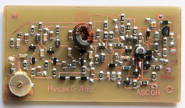
The input to the board is very sensitive to stray signals, I used pieces of PC board in the form of a box to provide 100% shielding. The board uses 1206 sized parts. The board measures 80 x 44 mm and is shown above, it was made using a laser printer to print a reverse track layout onto glossy PCB heat transfer paper, which in turn was ironed onto a double sided print board, then etched. The reverse side is a plain copper earth plane to take the ground connections to the square pads, which in turn were connected to the upper side with a short length of tinned copper wire.
The LM317 Voltage regulator uses a through hole part (top right hand corner). The transformer is wound on an FT37-43 core. In the lower left hand corner is a 6.8uH through hole RF choke. If a surface mount inductor is available it could be used. I used a 22 Ohm resistor at R38, 220 Ohm resistor at R6 and 3K3 resistors at R7 and R15.
The Q of the RF chokes was the subject of some discussion by Wes Hayward and others around the time of the QST article, my board uses Bourns CM252016-470KL (47uH), which have a minimum Q of 20 according to their specification sheet. The gain from my board gave rise to a higher level of "hiss" than I liked, even though the sensitivity was excellent and gave a lively S-meter which responded to signals as low as 1uV to produce 2 or 3 mm of movement - that was without the pre-amp switched on. I reduced the value of R2 from 2.2K to 1K to dampen the Q of L3 a little, which seems to do the trick. I've also changed the AGC threshold resistor (R6) from 270 Ohm to 220 Ohm and the memory capacitor from 4.7uF to 10uF to give a longer time constant. The image above is prior to making these changes. If your Hycas board has too much, or too little, gain it's worth experimenting with the resistors which dampen the Q of L2, L3 and T1.
The board is designed to be used with 50 Ohm filters, my IF filters are 500 Ohm so need a matching circuit comprising a 3uH coil in series with a 100pF capacitor to ground. The mute input is used to turn off the receiver when transmitting, it was not found necessary to also mute the AF pre-amp. There are no clicks or thumps when muting the receiver via this input.
Beware of tuning the input capacitor to 10 MHz (the local oscillator frequency on 160m), check on 160m that you haven't a high S-meter reading with no signal.
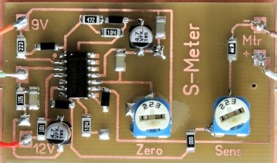
S-Meter
An S-meter driver based on the circuit shown on W7ZOI's web site is used. I designed a surface mount board layout, the circuit is the same as the ZOI one, except I added a sensitivity pot (22K) which is in series with a 12K feeding a 250uA meter, the value is select on test to suit your S-meter (typical values range from 8.2K to 22K with a 250uA FSD meter). The layout in the zip file includes component values. The board is double sided, with the underside being plain and used to provide ground connections. There is one "jumper" using a zero Ohm resistor to feed the output to the meter sensitivity pot. I also swapped the 12V rail decoupling capacitor from the original 100nF to a 4.7uF electrolytic. The meter does pretty much what you would expect and works very well when using a meter salvaged from an old Yaesu FRG7000. The board is set up by turning off the output of your signal generator, then set the "zero" pot (since renamed "Set Ref" on the layout) to give the same Voltage on it's slider as the AGC Voltage with no signal input to the receiver. The sens pot is then set to give S9 for -73 dBm input with the pre-amp and attenuators off.
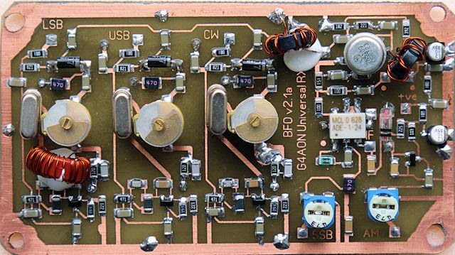
Product detector and BFO
The BFO has been updated from an earlier version, the oscillators are low harmonic and low phase noise designs. Each oscillator is isolated from it's neighbours by a 1N4007 diode acting as a PIN diode. I used through hole diodes, although SMD ones could be used. The output from T2 is +10 dBm into a 3 dB attenuator before feeding the ADE-1 double balanced mixer. The board is double sided with the reverse plain copper to provide ground connections via several through board links. The toroids can be secured with non acidic "704" silicon rubber adhesive (cheap on eBay). Note the board shown below is ver 2.1a, the later layout is 2.3
A 4 way, three pole, break before make switch is used to select the mode. Supply Volts to each oscillator and the IF filter relays are switched on one set of contacts using a pair of diodes to feed the supply to the IF filter board, the other switches the AM and product detector outputs. The third set of contacts switch the synth/display to indicate the correct mode.
The crystals can initially be set to the frequencies suggested on the circuit (if using the same Yaesu filters as I used), final adjustment is done with an audio spectrum mobile phone App to give a 1 KHz beat note on SSB and 750 Hz beat note on CW. The CW and USB oscillators may end up on the same frequency, but at least for the small additional cost they can be individually set.
Both the supply rail and the individual oscillator supplies need substantial decoupling, I used 100 uH RF chokes in series and a combination of a 1000 pF feedthrough capacitor, 0.1 uF disc ceramic and 10 uF radial lead electrolytic capacitors. An output for an AM detector is taken from the IF side of the mixer. It is essential the BFO is shielded to avoid oscillator leakage into the IF amplifier. Shielding was done using pieces of print board and was fairly easy although a little time consuming to construct a complete shield. If using double sided PCB for the shield, you need to ensure the copper on both sides of the board connect together. The top cover needs holes to allow for alignment of the trimmers.
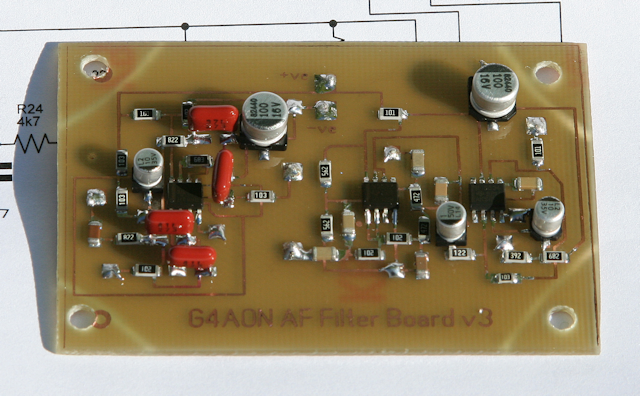
AF Pre-amp
Since originally building this receiver, I added a dual low pass and CW peak audio filter combined board. There is a page on this site describing this replacement board (Audio CW Filter from the index). A single pole c/o toggle switch has been added to the front panel which switches between wide and narrow audio filtering.
Audio output amp
A Velleman K4001 kit amplifier was used, the output coupling capacitor was replaced by one of 100 uF to reduce the bass content of the audio and a precautionary 0.01 uF disc ceramic capacitor added across the input terminal to reduce the risk of RF pickup. The amplifier is specified as 0.05% distortion and a maximum output of 3.5 Watts RMS into 4 Ohms.
Synthesiser and counter
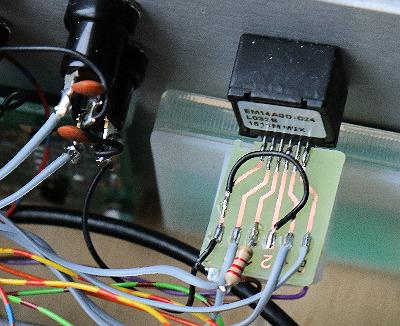
These originally were standard items from Cumbria Designs, unfortunately production of these items ceased some years ago. However I use an SDR Kits synth (image below) in my SSB transmitter and another builder used a similar one from SDR-Kits in his receiver and they work well. The synthesisers are based on an Si570 devices outputting +10 dBm into 50 Ohms. An optical tuning encoder is used, these are not normally included in the synth kits but are an essential extra. Mechanical encoders are not suitable.
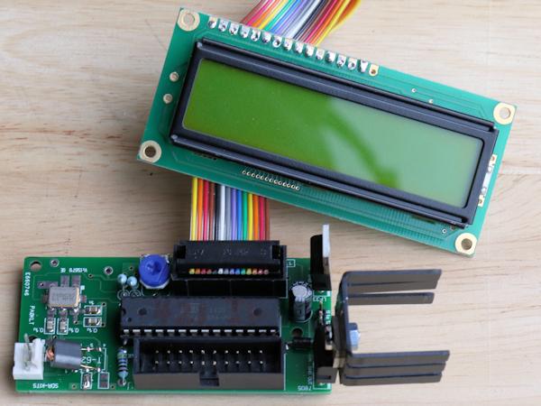
Connections to optical encoders can be a little tricky as the pins are easily broken and are close together. The solution is to etch a small print board and
to spread out the connections to pads (image below), there is an etching pattern in the zip file of board layouts.
Muting
The receiver is muted using the mute input of the Hycas IF board, open circuiting a ground connection in the associated transmitter raises the mute line to +12 Volts via a 22K "pull up resistor". Decouple the mute line with a series choke of 100 uH and 10 nF capacitors.
Alignment
Each band pass filter board was tested/aligned before adding them to the mother board. Those with trimmer capacitors were adjusted for maximum signal towards the higher end of each band, there was no need to stagger tune them. A final adjustment was done with the boards soldered in place. The IF notch filter was adjusted for minimum signal on 8.215 MHz with the 7 MHz band pass filter selected. A signal generator and spectrum analyser were used for alignment, if an analyser isn't available at a push a second receiver could be used.
The BFO was initially set to the predicted offset frequencies using a frequency counter connected to the output of the buffer stage, followed by a final adjustment with the screening cover in place using a smart phone running a free audio spectrum analyser program (AKLite, an iPhone App) to measure an offset from a signal generator, a 1 KHz audio tone in the case of LSB/USB and 750 Hz for CW. Check the BFO centres the IF filter correctly (more likely to be an issue with the CW filter) by picking a band with plenty of wideband "hash" and viewing the audio output via an audio spectrum analyser. Don't rush to buy one, there are some freeware programs that work well on a desktop PC and sound card, see: Spectrum Lab or Spectrogram
The capacitor on the input of the IF board needs to be carefully set, the tuning is quite broad, but be careful to not tune to the oscillator injection frequency on 160m (10 MHz for an 8 MHz IF), there is a lot of RF present and it's easily picked up by the IF board. The symptom of a wrongly tuned trimmer is the S-meter zeroing correctly on higher bands but not reading zero on 160m.
Issues and tweaks
Since building this receiver I've noticed a few issues, mostly related to the Hycas IF board. There is a known issue with the IF board where the AGC Voltage creeps down as the ambient temperature rises, this seems to be worse with a surface mount board. Q10 has a 1.5 Meg Ohm collector load resistor and responds wildly to even a few millivolts change on it's base. The effect can be replicated by warming the board to around 50 deg C, where the AGC Voltage drops from over 6 Volts to less than 1 Volt. The "work around" is to use a lower value of resistor at R6 than that suggested on the circuit. Dropping R6 from 270 Ohm to 220 Ohm works for me on both the surface mount board in this receiver and a through hole board.
The other IF board related issue is synth oscillator pick up, where you notice the S-meter reading around S5 on 160m with no signal. Tuning the input capacitor on the IF board may resolve the problem. Also try improving the screening of the output relays on the IF filter board and fitting a better cable or connectors that connect the synth in the receiver to the transmitter.
BFO leakage can be troublesome, even with the BFO board in what appears to be a fully screened box. After building the updated BFO board, I was surprised to see the S-meter rise when switching to LSB. Checking with an oscilloscope, there was around 5 mV of RF on the LSB oscillator supply line on the outside of the screened box. The issue arose from using double sided print board for the BFO box, the feedthrough capacitor for LSB had the extra decoupling capacitors soldered to the outside of the box, the CW and USB ones were on the inside. The outer copper on the print board was grounded around an inch or so away from the LSB feedthrough and that was sufficient to allow BFO leakage.
By using an AGC threshold resistor at R6 of less than 270 Ohms, the AGC line doesn't start to reduce in Voltage until the signal threshold is reached. With a 270 Ohm resistor there is no threshold, with 220 Ohms the threshold in my receiver (without the pre-amp) is -100 dBm (around 2 uV, S4 to S5). While the receiver sounds fine, it means the pre-amp is needed to display S-meter readings for weak signals that are quite audible. The problem is the S-meter is driven from the AGC line. The ideal solution is to use a separate amplifier strip for the S-meter, perhaps using an AD8307 logarithmic amplifier which is capable of measuring signals over a 90 dB range to an accuracy of around 0.5 dB Conclusion
The overall gain and noise level from this receiver gives very pleasant audio, the gain of the AF pre-amp produces just the right amount of audio. The AGC works very smoothly and the S-meter works well.
I haven't added DC wetting to the relays, so far I do not have problems with intermittent contacts, but others have reported issues when using relays without a few milliamps of DC current passing through the contacts.
Thanks to Dave, GM4EVS, for the neat diagrams and circuit analysis and to W7ZOI/WA7MLH, for the IF amplifier amd S-meter design. Also thanks to Markus, VE7CA, for the circuit ideas associated with the IF filters and IF amplifier, in particular the filter matching. Click here for a link to his HBR-2000 transceiver web page.
Resources
Obtaining parts can be hard work, the following sources may be useful:
2N5109 transistors, surplus S-meter from FRG7000, switches, PCB transfer paper, blank print boards, a development kit of SMD resistors and enamelled copper wire were from eBay. An alternative signal meter (reads 0 - 5) can be obtained from Maplin.
Toroids were from the GQRP Club, members can purchase parts at a good discounted price.
Mini Circuits mixers in small quantities can be obtained from www.rfmicrowave.it
The case, some SMD capacitors and SMD transistors were from RS Components (in the UK they currently have no minimum order value and free next day delivery).
Silver mica capacitors are available from Rapid Electronics in the UK.
The circuit diagrams and board layouts were drawn using the Windows software sPlan 7 and Sprint-Layout 6. Click here for a link to their site.
Elsie can be downloaded from here
SDR-Kits can be found here Click here for a link to their site
K1QW has a useful calculator for toroid inductors, it can be downloaded here.
Please do not build this design without checking the values for yourself, in particular the band pass filter components. The information is presented here to assist experienced constructors who may wish to build something similar, it is not suitable for novice constructors.


|
