RF BAND PASS
FILTER
The band pass filter unit is one of the most important parts of of the transceiver.
The PCB has four filters and space for a fifth, in case I decide to add an extra
band later. There are three parallel tuned circuits in each filter. Each tuned
circuit is coupled to the next by a capacitor (C2, C3). Diodes are used for input/output
switching. The filters have an input and output impedance of 50 Ohms.
 BAND PASS FILTER
The schematic shows the arrangement of the band pass filters and i/o switching.
To keep things clear and simple, only two bands are shown. You can have as many
as you like. When using ordinary Silicon diodes instead of proper PIN diodes,
it is very important to ensure that the DC current (more than 20mA in this circuit)
is greater than the RF signal current. The diodes in the filters that are switched
out, have several volts of reverse bias applied.
 BPF DETAIL
 BPF TOP VIEW
 PCB
PCB
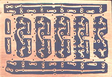
Hand drawn PCB layout for the BPF circuit board. I drilled the holes for the inductors
first, then drew the PCB tracks with an etch resist pen. It looks ugly but it
works quite well. I used a simple template to help drill the holes for the Toko
inductors.
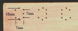 DRILLING TEMPLATE
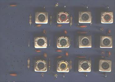
 TOKO 10K Coil
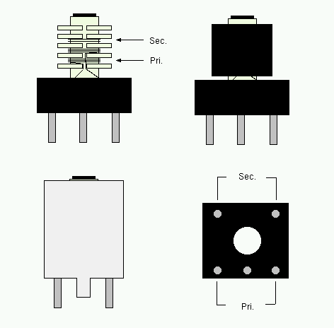
All of the inductors were wound on Toko 10mm formers that were recovered from
scrap equipment. These transformers are used in television receivers, car radios,
CB radios etc. Most of the Toko formers in the BPF were stripped from an old VHF
two way radio. The metal screening can on the Toko coils is secured to the plastic
base of the coil former by four dimples. They can be flattened by using a carpet
knife. It takes a bit of pressure so BE CAREFUL. Once the metal can is
out of the way, it is quite easy to remove the copper wire from the former. Use
a jewellers screwdriver to break the wire away from the pins, then unwind the
wire from the former. If there is a capacitor in the base of the coil, cut the
leads off and remove it. Use enamelled copper wire for the new windings. See table
below for details.
| Band |
T1 |
T2 |
T3 |
C1 |
C2 |
C3 |
C4 |
C5 |
| 80M |
21T,4T |
21T |
21T, 4T |
270p |
22p |
22p |
270p |
270p |
| 40M |
18T, 3T |
18T |
18T, 3T |
100p |
7p |
7p |
100p |
100p |
| 17M |
10T, 2T |
10T |
10T, 2T |
47p |
5p |
5p |
47p |
47p |
| 10M |
8T, 2T |
8T |
8T, 2T |
33p |
3p |
3p |
33p |
33p |
COMPONENT VALUES
The inductance of a Toko 10K coil is approximately: L in microHenries = (16 *
turns squared)/1000. Despite the fact that there are many different types of 10mm
inductors, this formula usually gives reasonably accurate results. This type of
coil has a tuning range of about 30%. I tested the BPF unit by connecting it to
the input of my nine band HF rig. The 40M, 17M and 10M filters worked perfectly,
the 80M filter was very lossy. I had to change the original 220pf capacitors to
270pF to get it working properly. I used ceramic disc capacitors for everything
except the 0.1mFd de-coupling capacitors. They are surface mount types, mounted
on the solder side of the board.
BACK TO HF TRANSCEIVER PAGE

[ About me
| Acronyms | CW
| Data Sheets | Docs
| Download | E-mail
| HOME | Ham
projects | Hobby circuits
| Photo galery | PIC
| QTH
photos |
Sign
in my guestbook | View
my guestbook ]
© 2001 - YO5OFH, Csaba Gajdos