Simple
430 SSB transceiver
by JF1OZL
1.Circumstances of this product.
I made and used 50MHz-ssb transceiver for these years. One night on the air,
my friend (JE3TXU/1:Mr.Haraguchi) said to me that ,"50MHz is easy to
build, and we must challenge to build 430MHz ssb ." This is my first
430-SSB-transceiver. this is very simple. This transceiver uses bilateral
theory in many parts of whole configuration.
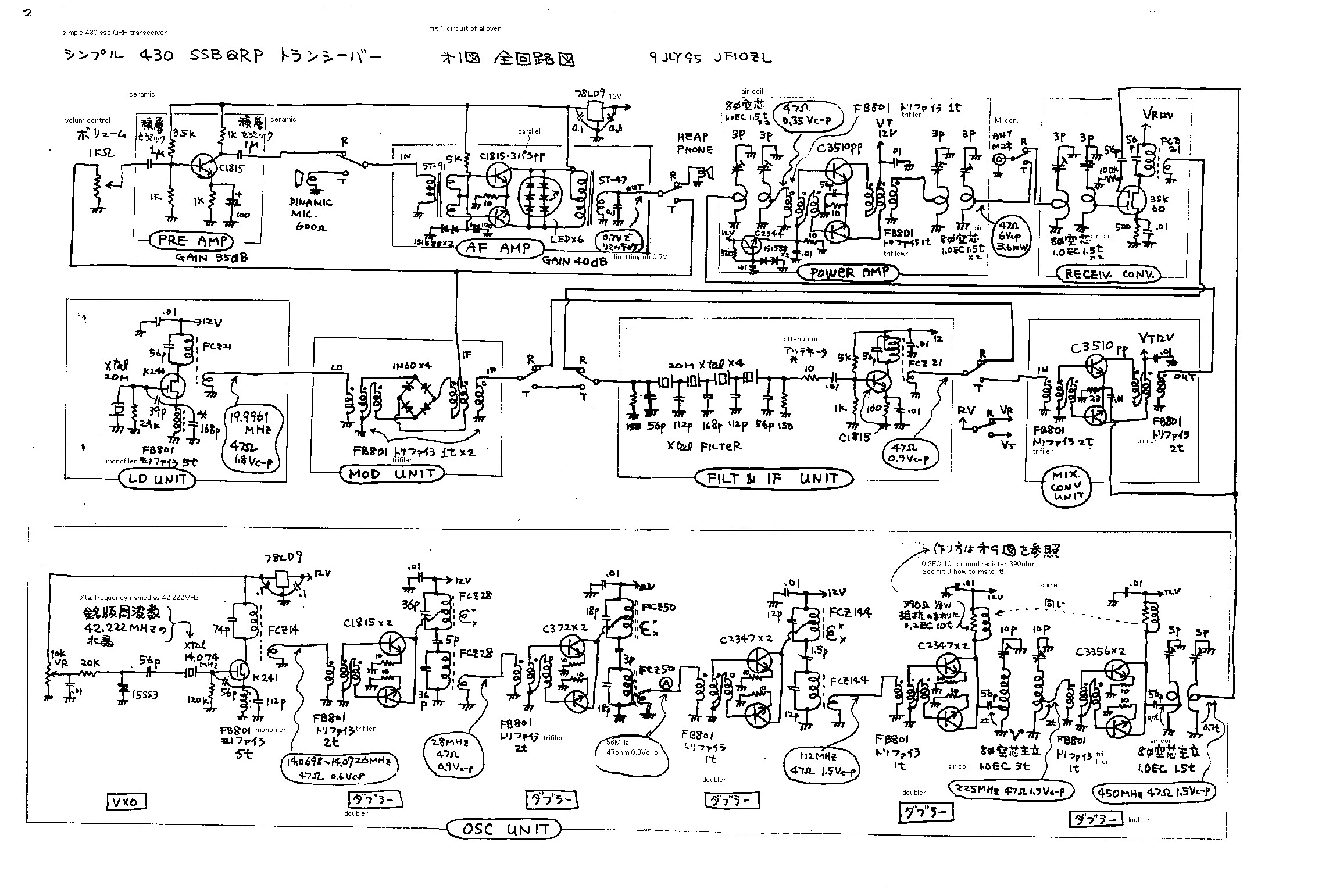
2. General construction of this transceiver
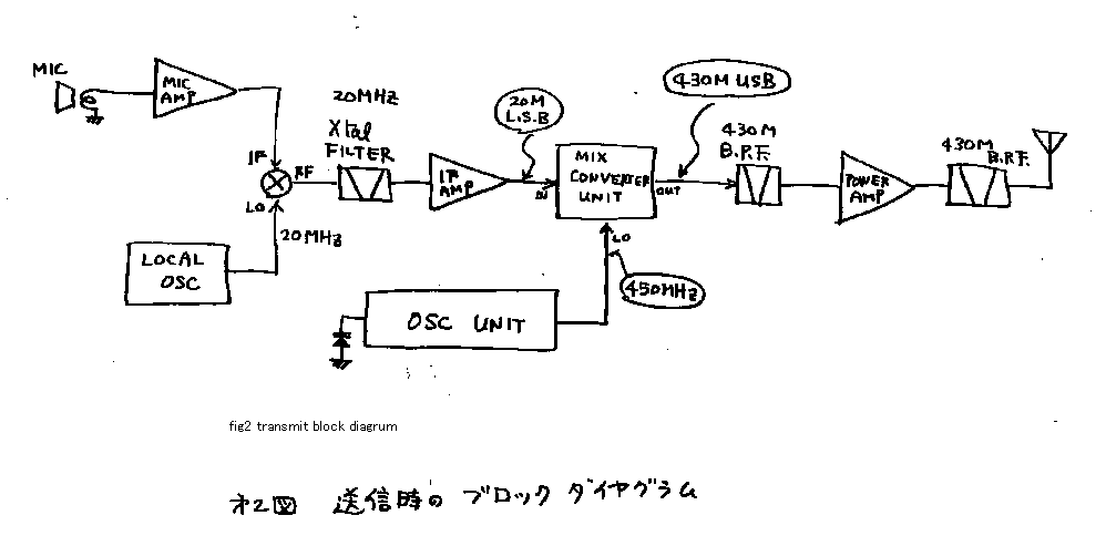
See fig 2! This is a diagram of transmitter. Audio signal is amplified by
audio AMP. It is inserted to IF-port of the DBM. On the other hand local oscillator
makes 19.9961-MHz signal. It is inserted on a local-port of DBM. Then I can
receive 19.9961-DSB signal on the RF-port of DBM. See fig4! Only lower side
band of DSB signal can pass through handmade-crystal filter. Therefore There
comes LSB-signal on the exit of the crystal filter. This signal is amplified
by IF-AMP. And it is inserted to the frequency converter. On the other hand,
14MHz VXO is constructed with the 42.222MHz named crystal. And it is multiplied
32 times. There comes 450MHz signal. At the converter 450MHz CW-signal and
19.9961MHz-LSB signal are mixed. There comes 430MHz-USB signal and 470MHz-LSB
signal. Only 430MHz signal can passes through the 430MHz band pass filter.
RF-AMP is only single stage. And after the signal passes through the BPF again,
it goes to the antenna. And radiated from the antenna to the air. I will Explain
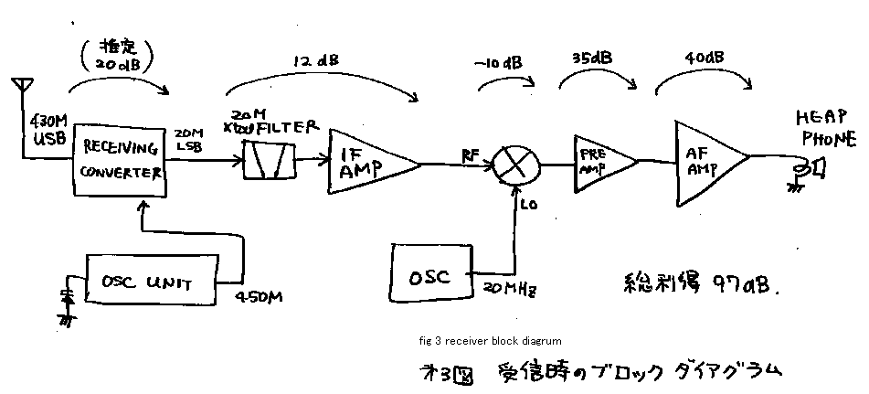
about the receiver. See fig 3! The signal from the antenna passes through
all each the circuits, as the counter direction from that of transmitter.
Two oscillators continue to work in both timing of receive and transmit. Therefore
I have no need to be afraid the changing of the frequency between receiving
and transmitting. Originally, by the way of development , the transmitting-converter
was used also as receive-converter. But the self oscillation has happened.
Therefore I made FET-receive converter another from transmitting-converter.
I can re-construct the transceiver easily, because it is constructed on the
mother-board. The AF-AMP has 40dB-gain. The gain of it is enough to the microphone-AMP.
But for the receiver, I need extra gain. Therefore I sat the pre-AMP. It gives
me more 35dB-gain only while receive.
3.Explanation of each block.
...About local oscillator unit....
Oscillator is constructed by 14MHz-VXO and five times (doubler=) double multiplier.
See fig 1. VXO is made of varicap-diode. I like to use a air-varicon(variable
capacitor is called so in Japan). But in this machine, I use the varicap-diode.
By using varicap-diode I can lay out the oscillator-unit and tuning-dial freely
in the case. When I use a air-varicon, I must locate the air-varicon near
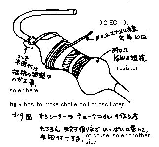
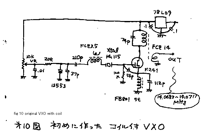
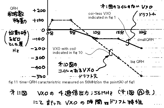
from the local-oscillator unit. See fig 10! Originally oscillator was constructed
by VXO using coil. Some operator send me the report that my signal has QRH.
Therefore I changed the construction. I used the coil-less-VXO. See fig 11!
Original-coil-VXO has 600Hz of QRH by 20 minutes. And the coil-less VXO is
improved in this point. By this VXO transmitting-frequency is tunable from
430.2352 MHz to 430.3256MHz. I bought the 42.222MHz third overtone crystal
by mail-order business and use it with it*s original frequency. The five-times-doubler
is constructed by push-push doubler. I learn about this doubler in the ARRL-handbook.
This type of doubler can work very sure. Because it works as C class amplifier,
it has no possibility to make useless self oscillation. And this type of doubler
can make very pure signal. Because it has double tuner on the corrector, it
avoid to through the original frequency, it avoid to product three harmonic
frequency. Yes you can believe it is the double frequency signal if you can
get some signal on the output of this circuit. I do not have a spectrum analyzer,
therefore I must choice such a reliable and easy to tune circuit. I want to
say one more this type of doubler is free from miss tuning. ....Five doubler
is constructed by the same circuit. But the dealing frequency is different
from each other. I must choose the transistor to match the frequency.
The ft-of the transistor must be 10 times bigger than the frequency dealt
by that circuit . Or else you can not get the enough electric output power
on the outside of the any types of amplifier or multiplier. Yes, it is very
important basic theory that you should care about it. Please take a red pencil
and please mark the upper line of your CRT display!
The first doubler makes 28MHz output, so it is made by 2sc1815(ft=80MHz).
The second doubler makes 56MHz output, so it is made by 2sc372(ft=200MHz).
The third doubler makes 112MHz output, so it is made by 2sc2347(ft=650MHz).
The fourth doubler makes 224MHz output, so it is made by 2sc2347(ft=650MHz).
The fifth doubler makes 460MHz output, so it is made by 2sc3356(ft=7000MHz).
You say that I do not keep 10 times theory? Yes my friends call me "About
man".HiHi.
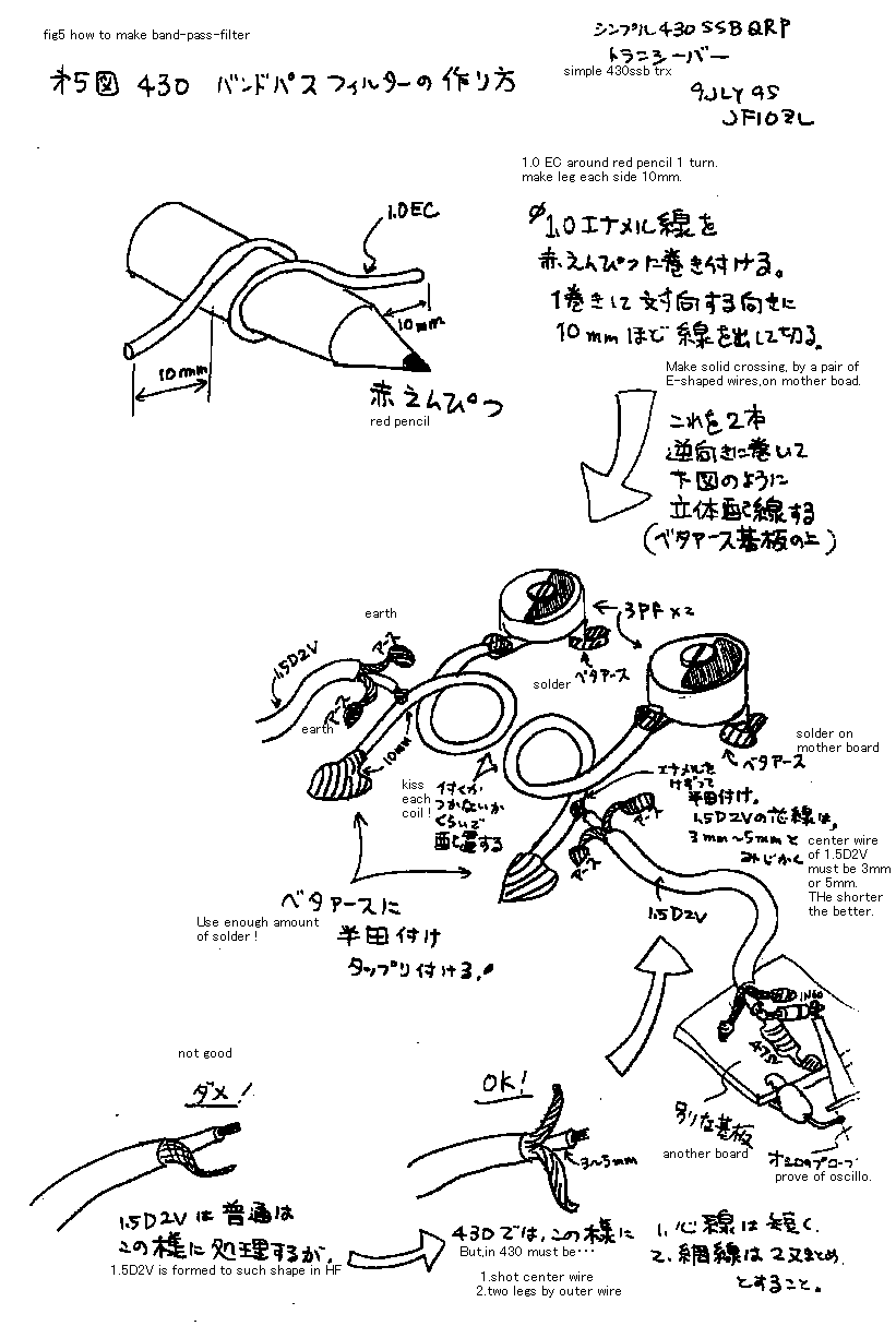
In the UHF circuit, the leg of the parts must be made very short, else you
meet the self-oscillation or lack of output-power. See fig5! It indicates
how to make 430 MHz band-pass-filter. In this filter, if you lay each coils
more closely, you can get more power. But too close lay out gives the poor
filtering character. If you take some space from each other, you can get cleaner
signal from it. But too much distance gives you poor signal strength. Therefore,
you must adjust the combine-factor of this band pass filter. In order to tune
the connection factor , solder the 1.5D2V(Japanese industrial standard calls
so) coxial cable wire on the coil. And on the other side of the cable, join
the dummy load and 1N60 diode and the prove of oscilloscope. If you joint
the dummy-load and the prove directly on the side of the band-pass-filter-coil,
the electro-magnetic force of 430MHz makes the influence to the prove of oscilloscope
and you can not measure correctly.
.....Audio frequency amplifier ....
Audio-frequency-amplifier is constructed by a normal transducer-push-pull-amplifier.
Three-series LED is connected on the first side of trans. The LED begin to
brink when it*s voltage becomes over 2 volts. Therefore it can limit the voltage
with 2 volts. Therefore this three LED array limits the voltage amplitude
on the first side of the output transformer with 6Vp-p. If you use more LED
, limiting point becomes bigger. When I speak to my microphone the LED lights.
It indicates this limiter makes it's job then.
....Local oscillator unit ...
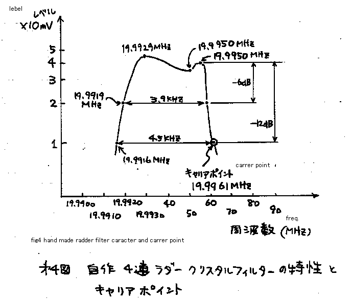
I must use the five 20MHz crystals to built this gear. Four of them is used
for filter. One of them is used for the local oscillator. See fig4! At first
I made a filter. And I tried some types of oscillator to make suitable 19.9961
MHz signal. FET-COLPITS-oscillator is used for the purpose. You must adjust
the capacitor between source and ground to get the suitable frequency. By
this method you can make SSB-signal with a set of 5 the same crystals.
....modulator unit ...
Modulator unit is made by diode-ring-modulator. You must limit the audio signal
smaller than half(-6dB) of the carrier signal. Else DSB signal becomes dirty.
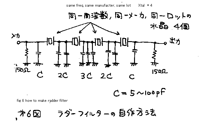
....ladder type crystal filter ...
See fig 6! Join four the same crystals series. And join the nine same capacitors
between the crystals and the ground. The capacitor becomes bigger , narrower
the pass band becomes. But you cannot change the center of pass band. It is
decided by the original frequency of the crystal. Put the attenuator of resister
on the front and end of the filter. Else shape of pass band becomes bad. This
filter has the loss about 10dB. So you must use IF AMP after it, to cover
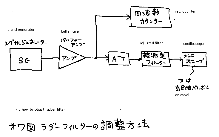
the loss of the signal. See fig 7! It indicates how to adjust the filter.
You can plot the characteristic of the filter by this system. If the pass
band is wider than 4KHz, change the capacitors for bigger one. And try again.
If the band pass is narrower than 2.5KHz , change the capacitors to smaller
one. It may need 6 hours to make this adjustment with this signal oscillator
and frequency counter.
If the filter is narrower than 2KHz your transmitting-voice may become like
nose-closed-person, because the upper half of your voice be cut. If the filter
is wider than 5KHz, your rig may have QRM on the crowded band , because the
filter can pass the neighbor side signal. Therefore the pass band of the filter
should be adjusted between 2.5 to 4KHz.
...IF AMP ....
Next stage is IF AMP. If you can complete these units, please test it! Contact
the vinyl wire on the output of IF AMP! Make loose contact between the wire
and some kind of radio. The radio must be wide band type to receive the IF
frequency 20MHz in this case. The radio must have BFO(beet-frequency-oscillator)
on it to demodulate the SSB signal. If you can get some helper, put the microphone
of the transmitter in front of the mouth of your helper! If you can not get
any helper, please use the tape recorder. Adjust the carrier-point! If the
carrier is located too far from the band-pass of the filter, you cannot hear
some low voice clearly like the Buuuu or wooooo, because the lower spectrum
of the voice is cut. If the carrier is located too near from the band-pass
of the filter, you cannot hear the high voice like sha syu syo.
.... converter ....
Converter is constructed by the push-pull-active-single-balanced-mixer. Also
in the case of this mixer, the IF signal must be smaller (lower signal strength
level) than the local signal. Therefore I put the 10-ohm-resister in front
of the IF AMP. In stead of this tuning, you can add one more amplifier on
the local oscillator. It is a matter of total signal revel planning as the
transmitter. ............I will explain about the tuning of emitter resister
of the converter. The smaller resister if you use, the conversion-gain becomes
bigger. But it may need more power as the local signal. The bigger the resister
if you use ,the smaller level of the oscillator can drive satisfactory this
converter. But the conversion gain become small in this case. In this machine
I made, the conversion gain becomes -8dB. Its loss is smaller than diode converter.
But the conversion gain is far smaller than the normal nallow band converter.
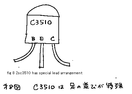
In this converter you must use high ft-transistor. I use 2sc3510(ft=3500MHz).
See fig 8. Emitter-base-collector are printed on the package of this transistor.
I guess the designer of this transistor (Technika of Hitachi) may be kind
person.HiHi
... power AMP ....
Power AMP is constructed by the wide-band-push-pull-A-class AMP. This type
products very clean signal. But ft of the transistor must be bigger than ten
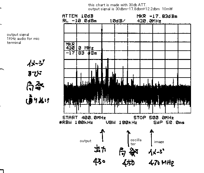
times of 430MHz. Output-power of AMP is 10mW QRPP. Please look the last figure
of this page. I measured the total transmitting signal frequency character
with spectrum analizer of Japanese amateur radio association. The through
of local signal 350MHz , and the difference side of the converter 470MHz is
suppressed 40dB or more than the transmitting signal of 430MHz.
....Receiver ...
In the receiver, all the circuit is used as the counter direction from the
transmitter. All the circuits is changed by small relay. Only the front converter
of the receiver is constructed by two gate FET. It is normal usage of this
FET, that is developed to use the front converter of TV receiver set.
....4.... When I use this transceiver .....
I make some local-expedition, on the hill, about 500 meter high, on the Tsukuba
mountain. With 10 element Yagi-antenna, I could make QSO with the stations
on Yokohama and Tokyo. I got 51 to 57 report. MY rig is 10 milliwatt QRPP,
but I can use many element-Yagi in this band easy. 10mW operation with 10dB
gained antenna has the same meaning with 100mW dipole operation. Let's challenge
430MHz! Don't care of your mistake! .
At the end of this page ,I will show you the character of the transistors
to help your own choice.
2SC1815: Maker= Toshiba: usage Low frequency amplifier general use: Vcbo=60V:
IcMAX=150mA: PcMAX=400mW: hfe=70 to700: fT=80MHz
2SC3510: Maker= Hitachi: usage UHF ,VHF amplifier: Vcbo=20V: IcMAX=50mA: PcMAX=600mW:
hfe=30 to200: fT=3500MHz: Typical 10.5dB on 900MHz
2SK241: Maker= Toshiba: usage= FM VHF Radio frequency amplifier: Mos N channel:
VMAX=20V: Idss=10mA: gm=10mSmax: Cis=3pF: Crs=0.035pF: Power gain 28dB typical
on 100MHz
3SK60: Maker= Hitachi: usage= VHF Radio frequency AMP: Mos : VMAX=15V: Idss=12mAmax:
gm=16mS typical: Cis=5pFmax: Crs=0.015pF: Power gain 24dB typical on 200MHz
2SC2344: Maker= Sanyo: usage High voltage switching ,low frequency amplifier
: Vcbo=180V: IcMAX=1.5A: PcMAX=25W: hfe=60 to200: fT=100MHz
2SC372: Maker= Toshiba: usage =LF/HF amplifier specially designed to use IF
of MW radio: Vcbo=35V: IcMAX=100mA: PcMAX=200mW: hfe=70 to 240 : fT=200MHz
2SC2347: Maker= Toshiba: usage =UHF oscillator ,VHF mixer: Vcbo=30V: IcMAX=50mA:
PcMAX=250mW: hfe=20min: fT=650MHz: Cob=1.5pF
2SC3356: Maker= NEC: usage =HF low noise amplifier: Vcbo=20V: IcMAX=100mA:
PcMAX=200mW: hfe=50 to300: fT=7000MHz: Typical Noise figure=2dB on 1000MHz
![]()
Download the schematic
Download the transmit block diagram
Download the receiver block diagram
Radder filter caracter and carrer point
How to make radder filter
How to adjust radder filter
How to make band-pass filter
Original VXO with coil
Time-QRH caracteristic
measured on 56MHz
Output spectrum diagram
 |
 |
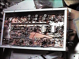 View of whole this transceiver without top cover |
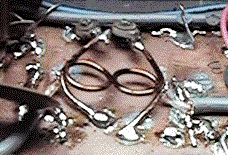 View of 430 band pass filter |
![]()
[ About me
| Acronyms | CW
| Data Sheets | Docs
| Download | E-mail
| HOME | Ham
projects | Hobby circuits
| Photo galery | PIC
| QTH
photos |
Sign
in my guestbook | View
my guestbook ]
© 2001 - YO5OFH, Csaba Gajdos