original idea and concept by Dany Bavin.
|
|
|
|
This project comes as a KIT. It includes these components:
- Low-cost DMM (digital multimeter) M830D
- TX (transmitter) circuit and wireless module TX-433. These are mounted within the DMM housing.
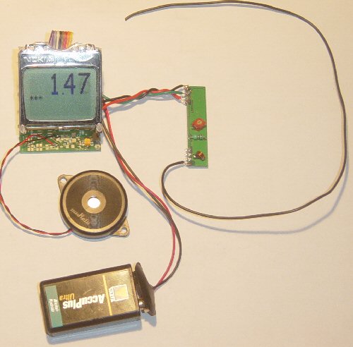
- RX (receiving) circuit with a wireless module RX-433, LCD and piezo buzzer.
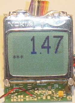
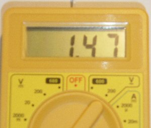
The general idea is to read all LCD data from a cheap DMM (directly from its main chip.) This data is sent and received by wireless modules, read by the RX circuit and then displayed again. Sounds pretty easy, not?
Here are the technical specifications:
- Low power operation (8-10 mA @9V) with PIC 18F452 (TX) and 18F2550 (RX) microcontrollers running at 4 MhZ.
- Sampling rate: around 3 samples/sec.
- Max. distance between the RX and TX circuits: 30m indoors and 100m outdoors.
- Software is 100% upgradable with a simple bootloader.
- Low power LED blinks when sending / receiving data.
- TX circuit: PCB Dimensions: 30 x 31 mm or 1"18 x 1"22, weight: 8 grams.
- RX circuit: LCD contrast adjustable by user.
- RX circuit: PCB Dimensions: 40 x 41 mm or 1"57 x 1"61, weight: 10 grams.
Hex files available. Last update: June 1, 2006. |
|
Main Connections:
RX circuit diagram (top view) |
Header pinouts * |
|
| JP1 |
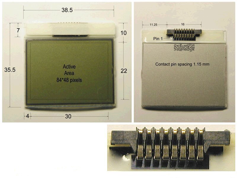
Nokia 3310 LCD |
|
JP2 |
RS232 interface |
|
JP3 |
RX module, supply, I/O |
| |
|
|
|
|
|
|
|
| 1 |
VDD, +5V |
|
4 |
TX |
|
1 |
+9V input from battery |
| 2 |
SCLK |
|
3 |
GND |
|
2 |
input from RX-433 module |
| 3 |
SDA |
|
2 |
RX |
|
3 |
NC (no connect.) |
| 4 |
D/C |
|
1 |
+5V |
|
4 |
GND (to battery and RX-433) |
| 5 |
CS |
|
|
|
|
5 |
LCD contrast adjust input |
| 6 |
GND |
|
|
|
|
6 |
+5V output (to RX-433) |
| 7 |
Vout |
|
|
|
|
|
|
| 8 |
RES |
|
|
|
|
|
|
| |
| * Note: pin 1 is marked by a red arrow in the diagram |
|
|
TX circuit diagram (top view) |
Header pinouts * |
|
| JP1 |
to TX-433 module |
|
JP2 |
RS232 |
|
JP3 |
LCD inputs |
|
JP5 |
LCD inputs |
| |
|
|
|
|
|
|
|
|
|
|
| 1 |
+V |
|
1 |
+V |
|
1 |
+V |
|
8 |
A2 |
| 2 |
TX_out |
|
2 |
RX |
|
2 |
G2 |
|
7 |
B2 |
| 3 |
GND |
|
3 |
GND |
|
3 |
C3 |
|
6 |
C2 |
| |
|
|
4 |
TX |
|
4 |
A3 |
|
5 |
D2 |
| |
|
|
|
|
|
5 |
G3 |
|
4 |
E1 |
| |
|
|
|
|
|
6 |
COM (GND) |
|
3 |
G1 |
| |
|
|
|
|
|
7 |
NC, no connect. |
|
2 |
F1 |
| |
|
|
|
|
|
8 |
BP, backpane |
|
1 |
A1 |
| |
|
|
|
|
|
|
|
|
|
|
| |
|
|
|
|
|
|
|
|
|
|
|
|
| JP6 |
LCD inputs |
|
JP7 |
LCD inputs |
|
JP8 |
LCD inputs |
| |
|
|
|
|
|
|
|
| 8 |
Buzzer in |
|
1 |
B1 |
|
1 |
B3 |
| 7 |
Lobat in |
|
2 |
C1 |
|
2 |
D3 |
| 6 |
dp1 |
|
3 |
D1 |
|
3 |
E2 |
| 5 |
dp2 |
|
|
|
|
4 |
F2 |
| 4 |
POL |
|
|
|
|
|
|
| 3 |
AB4 |
|
|
|
|
|
|
| 2 |
E3 |
|
|
|
|
|
|
| 1 |
F3 |
|
|
|
|
|
|
| |
| * Note: pin 1 is marked by a red arrow in the diagram |
|
| |
DMM LCD connections |
 |
| |
|
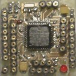
| DMM M830D chip pictures |
DMM M830D chip pinout (top view) |
 |
 |
 |
RS232 interface: JP2 provides the interface to connect to your COM port and hyper terminal. Also used for bootloading (module software update.) Check under the download section below for the latest version. Bootloading of the HEX-file can be done with Tiny Bootloader.
RX circuit, LCD contrast Adjust: Connect pin 5, JP3 to +5V before powering up. Release when the desired the contrast is reached.
Downloads: right-click & save as
Info & datasheet:
Screenshots:
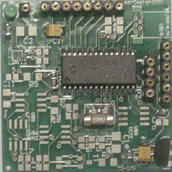
TX circuit (top view) |
RX circuit (top view) |
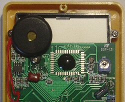
DMM (back cover removed) |
RX circuit (working) |
|
|
|
 |
| WMM KIT 1 contents: picture |
WMM KIT 1 contents: description |
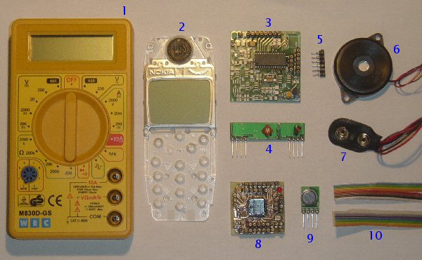 |
- DMM M830D
- Nokia 3310 LCD
- RX circuit
- RX-433 module
- SIL contacts
- Piezo buzzer
- 9V battery clip
- TX circuit
- TX-433 module
- Flatcable
Blue= TX (DMM, TX circuit and module)
Black= RX (RX circuit and module, LCD, Buzzer) |
Tools:
The PIC code was made with the PCWH CCS compiler ($425,-); you can install Microchip's MPLAB IDE (click on the link and you can get it for free) with it to get things running smoothly.
Bootloading of the modules is done with the excellent Tiny PIC bootloader, through RS232 (JP2).
Eagle 4.11e was used for the schematic & PCB layout.

[ FREE Ham Radio Data Center [ FREE Ham Radio Links Directory [ About me | Acronyms | CW | Data Sheets | Docs | Download | E-mail | HOME | Ham projects | Hobby circuits | Photo galery | PIC | QTH photos |
Sign in my guestbook | View my guestbook ]
© 2001 - YO5OFH, Csaba Gajdos