|
|
|
Morse Code Speedometer
using the 16F84 PIC
This program uses a 16f84 to wait for 10 minutes after the switch
input is pressed - it will wink an LED once a second - then when 10 minutes have elapsed, the PIC will send a Morse code message through
both the piezo speaker and an output transistor. The Morse message can be up to 60 characters long. When the timer is not in use the
PIC is put to sleep to save power and reduce interference. There is also an LED output - the LED is "winked" once per second while the
delay proceeds to let the user know that the PIC is active.
There is another output pin used to control a relay - this might be useful for non-ham apps of the timer such as an EPROM eraser timer?
The timer can be automatically retriggered after the initial delay by connecting the retrig pin to +5V. The timer delay OR the message
send can be interrupted by a press and release of the switch input. The timer can output a once a second click to the piezo if the
click input is connected to +5V
The message, the delay time and the code speed are stored in eeprom memory and can be changed using a PIC programmer or using
a nasty little recording routine stored in the PIC. This routine uses the click and retrig inputs to set the various parameters.
The eeprom change routine (MENU) is entered with a press and hold of the switch input for 2 seconds - after this initial hold, the
PIC will send:
MIN? x (where x is the current minute delay)
The user can then use the retrig input to decrease the delay by connecting it to +5V OR use the click input to increase the delay by
connecting it to +5V. The PIC will send the changed minute delay and then check the inputs again. To exit the routine and save the
changed minute value, press and release the switch input. The PIC will then send:
SEC? y (where y is the current second delay)
Again, the retrig switch decreases the delay when connected to +5v, the click switch increases the delay when connected to +5V. Pressing
and releasing the switch input will save the changed value and then the PIC will send:
DL? z (where z is the current dit length in ms)
Connecting the retrig switch to +5V will decrease the dit length, connecting the click switch to +5V will increase the dit length.
The maximum dit length is 80 ms (15 WPM). The minimum dit length is 30 ms (40 WPM). A press and release of the switch input will
save the dit length in eeprom and then the PIC will send:
MSG?
If the switch input is pressed and released, the message record routine will be skipped. If either the retrig or click switches
are set to +5V, the first character in the message will be played. The user can then changed this character (retrig to +5v goes up the
character table, click to +5V goes down the character table). Proceed to the next character with a press and release of the
switch input. Exit the message record routine with a 2 second press of the switch input. The PIC will then send:
DONE
Note that there are two special characters used in the recording process: a word space is denoted with a
run together SP (....--.). Then end of the message is denoted with a run together END (.-.-..).
The size of the message is limited to 60 characters - the recording routine should automatically bail out when the 60th character is
entered. The PIC 16F84 has 64 bytes of eeprom - 1 is used for the minutes, another for the seconds, a third for the dit length
and the last for the end of message byte.
Note that all of the routines will "wraparound" either from high to low OR low to high when the user reaches a
limit (ex, increase the delay from 99 minutes and the delay will wrap around to 0).
The easier way to change any of these parameters is to simply edit the EEPROM data at the end of this file and then use the programmer
to burn it into the 16F84 EEPROM. The message can be entered in ASCII (upper case letters only). Some of the special characters
should be entered in numerical format.
An easy way to reset the timer is to power off, then press and hold
the switch input while powering on the timer. This will reset the timer to a 10 minute, 0 second delay at 15 WPM with a single period
(.-.-.-) as the only message.
Possible Enhancements:
-
use a 32.768 KHz crystal instead of the 4 MHz crystal to save power
-
get rid of the end of message byte usage at the full limit of the
eeprom - this would allow another character in the message or 61 total characters.
-
some new or different way to enter the timing and message parameters
which is less ponderous and more intuitive.
Click here for schematic
, sourse code and readme.txt
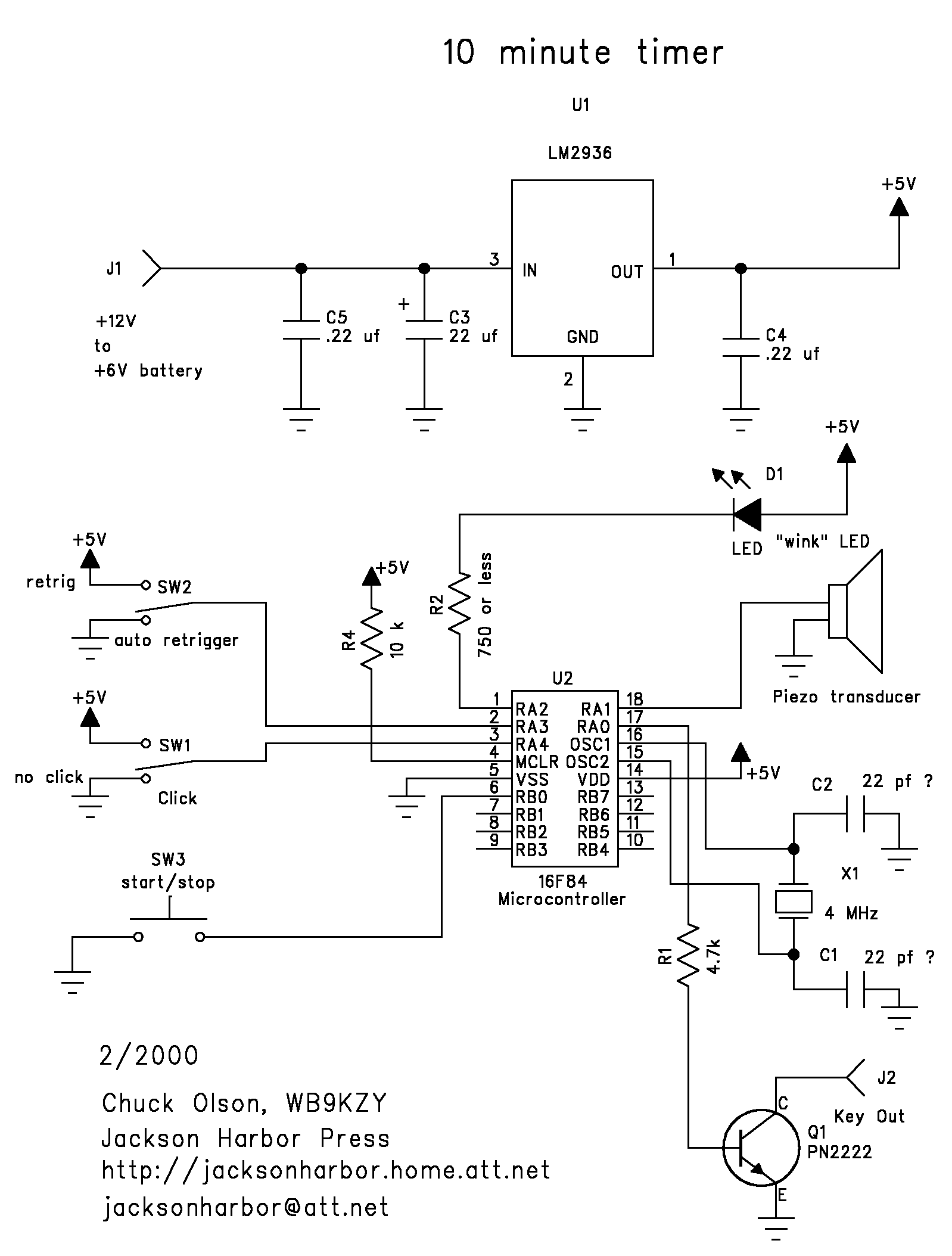
PIC pinout:
| Pin |
Name |
Function / Connection |
| 1 |
ra2 |
wink LED output |
| 2 |
ra3 |
auto timer retrigger, 1=retrigger 0=terminate |
| 3 |
ra4 |
second click off, 1=click on, 0=click off |
| 4 |
MCLR |
pulled up to +5V with a 10K resistor |
| 5 |
Vss |
Ground |
| 6 |
rb0 |
retrig input, 1=auto retrigger of delay, 0 = single delay |
| 7 |
rb1 |
no connect |
| 8 |
rb2 |
no connect |
| 9 |
rb3 |
no connect |
| 10 |
rb4 |
no connect |
| 11 |
rb5 |
no connect |
| 12 |
rb6 |
no connect |
| 13 |
rb7 |
timer output to the relay driver transistor |
| 14 |
Vdd |
+5V |
| 15 |
osc2 |
connected to 4 MHz xtal & 22? pf cap |
| 16 |
osc1 |
connected to 4 MHz xtal & 22? pf cap |
| 17 |
ra0 |
keyed output to the keying transistor |
| 18 |
ra1 |
piezo speaker output for sending the speed in Morse & click |

[ About
me | Acronyms | CW
| Data Sheets | Docs
| Download | E-mail
| HOME | Ham
projects | Hobby
circuits | Photo galery
| PIC | QTH
photos |
Sign
in my guestbook | View
my guestbook ]
© 2001 - YO5OFH, Csaba
Gajdos |