Serial Voltmeter using the
PIC16C71
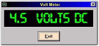
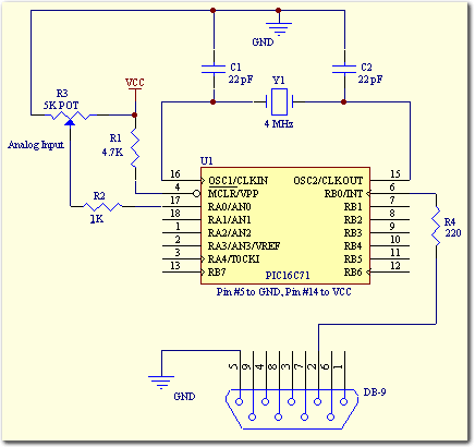
Building a serial voltage meter to measure from 0 to 5 volts DC is actually pretty easy. Using MeLabs PicBasic, and Microsoft's Visual Basic Version 5 Pro. You need Visual Basic Pro version because you will have to use Basic's MSComm control. This control is not available in the Visual Basic 5 "Learning" Edition. The PIC16C71 simplifies the task even more by having a built in A/D converter. Pins 17,18,1,2 are the analog inputs AIN0,AIN1,AIN2,AIN3 respectively.
The software for the serial voltmeter monitors the serial port for incoming information sent by the PIC micro. Once received, the displayed result is calculated by taking the value received and multiplying it by 0.02. The PIC16C71 A/D converter is the successive approximation type and provides an 8-Bit result. With only an 8-Bit result our range is limited from 0 to 255 that represents from 0 to 5 volts respectively.
Here is the schematic for the PIC16C71
Here's the PicBasic code:
' Access PIC16C71 A/D using Peek and Poke
Symbol ADCON0 = 8 ' A/D Configuration Register 0
Symbol ADRES = 9 ' A/D Result
Symbol ADCON1 = $88 ' A/D Configuration Register 1
Symbol SO = 0 ' Serial Output on port B0
poke ADCON1, 0 ' Set PortA 0-3 to analog inputs
poke ADCON0, $41 ' Set A/D to Fosc/8, Channel 0, On
Loop:
poke ADCON0, $45 ' Start Conversion
pause 1 ' Wait 1ms for conversion
peek ADRES, B0 ' Get Result to variable B0
serout SO,N2400,(#B0,10) ' Send variable to serial out
goto Loop ' Start over again
The code was written using Micro Engineering's PicBasic and is really simple. Using the PEEK & POKE commands in PicBasic we can directly access the internal AD registers of the PIC16C71 and the port A pins. After setting up the AD registers for using AN0 to accept our analog input, the program stays in a simple loop and continuously sends out the analog value sampled on pin #17 RA0/AN0.
Here's the Visual Basic code:
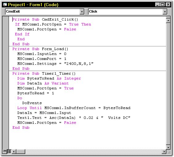
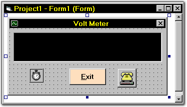
By building a simple form using Visual Basic like the one above we just place the MSComm Control, a timer, a text window and a button that we use to exit the program. By referring to the code window above and Form1 you can build your own VB application just like the one we did here.
If you prefer to use a different com port, it's simple to change the code as shown above where we select CommPort 1. Simply change this to whatever com port you prefer. Notice the code line Text1.Text = Asc(DataIn) * 0.02 & " Volts DC". This line of code transforms the incoming data from the PIC into a value that we can display in the text box (the black area). Since the PIC16C71 AD converter has an 8-bit resolution we know that we can only have 256 possible combinations, ( 0 to 255).
Since 5 volts divided by 256 = 0.0195 we know that a returned value of 250 would equal 4.87 volts, or 250 X 0.0195 for 4.87V. A value of 255 would represent close to 5.0 volts (4.9725), and a value of 52 would indicate 1.014 volts.
8-Bit Resolution: For most purposes 8-bit resolution is more than adequate. With 8-bit resolution we're able to measure the analog input values in 0.0195 volt increments. We have 0 representing 0-volts, and 255 representing 5-volts. Our actual resolution is 0.0195, or 19.5mV. With 256 possible readings starting at 0 and going up to 5V at 19.6mV per reading, this is more than adequate for most applications.
OK, so why did I use a value of 0.02 for my calculation...? I rounded-up the number to 0.02 because I used my Fluke Voltmeter to get a precise reading while my circuit was in operation. I found that by using 0.02 my results were more accurate. Your circuit may differ slightly since no two devices ever seem to be created equally. It's a good idea to experiment a little, and use a good quality voltmeter to tweak your calculations down to better accuracy.
This is a fun project and has plenty of room for improvement, especially the visual basic code. It is however a good starting point for someone new to the concept of analog to digital conversion using the PIC16C71 microcontroller. It's a good introduction to interfacing the microcontroller to the outside world as well.
NOTE: The Visual Basic Software provided here is 32-Bit and runs on Window 95, or Windows 98, using Com1.
Here's the HEX file for the PIC16C71 ready to burn into your PIC16C71. Click HERE for the HEX file.
Here's the VB5 code. This is the full Installation/Setup program for the project shown above. Click HERE for the Visual Basic files.
If you would like to design your own version, or just have the VB code to play with, here's a different version (without the timer), submitted by Bob Katter. This one includes the complete VB code for a serial voltmeter. Click HERE to download Bobs version.
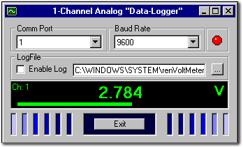
Check out our new Data-Logging software for an RS-232 Terminal & Serial Voltage Meter with full viewing and logging capabilities. Click here.
