 |
LCD Serial Terminal
Introduction:
In the 1980s a serial terminal was a big thing with a picture tube
and keyboard. You used it to communicate with a computer by RS-232 cable
or with a modem. In this century, we still sometimes have need for a serial
terminal, and we’ll typically use a personal computer running a
terminal program (Hyperterminal, bundled withWindows, is a terminal program).
This project is a self-contained serial terminal using a PIC16F84 microcontroller
chip, an inexpensive LCD character display, a keypad, and very little
else. It is full-duplex, meaning keypresses cause RS-232 output, and RS-232
input makes characters appear on the LCD. If you connect the RS-232 output
to the input you can see the keys as you press them, without connecting
to anything else (that’s called “looping back”).
Project Description:
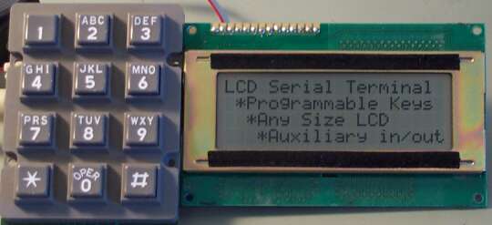
The picture above doesn’t show the electronics, just a keypad
and LCD display. The electronics is on a small board behind the LCD. This
LCD is a 4 line by 20 character intelligent LCD display. Displays from
1x8 to 4x20 or 2x40 and pretty much anything in between are compatible.
I paid less than US$10 for this display from All Electronics. The keyboard
you use should be a matrixed keyboard or keypad with up to 5 rows and
4 columns (20 keys maximum).
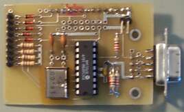 This small PC board is the terminal itself. Someday I will
document a PC board design, but currently I am only making available the
schematic diagram, source code for the PIC16F84, and compiled hex code
for a typical configuration so you can quickly test it out. The source
code is in C and very easily configured for different baud rates, LCD
and keypad configurations. The program should be compiled with Hi-Tech
PICC. A free version supporting the PIC16F84 called “PICLITE”
is available and works fine.
This small PC board is the terminal itself. Someday I will
document a PC board design, but currently I am only making available the
schematic diagram, source code for the PIC16F84, and compiled hex code
for a typical configuration so you can quickly test it out. The source
code is in C and very easily configured for different baud rates, LCD
and keypad configurations. The program should be compiled with Hi-Tech
PICC. A free version supporting the PIC16F84 called “PICLITE”
is available and works fine.
The mapping of the keys is fully configurable, and each key can also be configured for one of four different modes. Each key is allowed to have a primary code and a secondary code. Depending on what mode is chosen, the secondary code might be sent when the key is released, or when the key is held more than one second, etc. Key repeat is also programmable, and each key can have a different mode.
Many cursor movement features are implemented, all the standard ones (backspace, carriage return etc.) and if you tell the program your LCD format, text will flow from line to line.
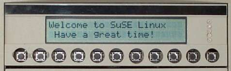 |
Every pin of the PIC16F84 is used, and some pins are used for 4 functions, through multiplexing the LCD, keyboard drive, and auxiliary input and output, using a feature I call “supermultiplexing”. I intended the auxiliary outputs to drive LEDs. The picture above shows a terminal mounted in a computer’s drive bay, see the five LEDs on the right side. The LEDs are time-sliced, so the pins are not dedicated all the time, so the LEDs will show a faint glimmer when off. Nonetheless, it’s a useful feature. Auxiliary inputs should be connected through a 10K resistor and will read high if left floating. One PIC pin is completely free and is configured as an output. The source code is easily modified if you need more pins and can sacrifice keypad columns.
Technical Notes:
Baud rates are chosen in the program before compiling. If you use
a 4 MHz crystal the maximum baud rate is about 2400 baud. Actually you
can get 2400 baud with a 3.58 MHz crystal. If you need 9600 baud you can
use a 14.318 or 16 MHz crystal, even though the PIC16F84 is only rated
for 10 MHz(or use a PIC16F84A). “Funny” baud rates are possible,
within limits any baud rate can be used. It is not possible to have split
(different baud rate for send and receive) rates. The PIC16F84 does not
have a hardware UART (serial port) so each bit must be done in software
using a method called “bit-bashing”. I used the timer-based
interrupt to manage the timing. This limited the maximum baud rate, but
the code is less messy using the timer interrupt.
The circuit requires a 5 volt DC power supply at a few milliamps. Although the PIC16F84 can run from 4 to 6 volts, the LCD contrast varies wildly with voltage. In the schematic I have shown LCD pin 3, the contrast pin, grounded. This might give you too dark a display. Connect it to ground through a 470 Ohm or 1K ohm resistor to lighten the display.
RS-232 is supposed to have +12 and -12 volts. This circuit does neither. Driving long, noisy lines could be troublesome. The receive pin is a Schmitt Trigger so it should reject most sources of noise, but if you have problems you could terminate it with a 4.7K resistor to ground at the board.
Supermultiplexing is not shown on the schematic. It is available on 5 pins (RB3-7). For output, connect LEDs through resistors(minimum 220 Ohms). The are commanded with control-P followed by the binary pattern you wish to output. The upper 5 bits of the byte you send will be output, and the lowest bit is sent out RB0. The other two bits are ignored. For input, hook to pins RB3 through RB7 through 10K resistors. You can use switches to ground, sense logic levels, or even sense 12 volt logic in an automotive application. Read the pins with control-N. A byte will be sent out showing the state of PORTB. The bottom 3 bits are not cleared so you should ignore them.
The source code is heavily commented so you should consult it before asking questions!
Timing is based on the crystal. You may substitute a ceramic resonator instead of a crystal, the accuracy of a resonator is adequate. Although a PIC can use an RC oscillator, it should not be used in this circuit, your baud rate would not be accurate. Use a crystal or resonator.
Download:
The schematic in pdf format: lcdterm.pdf
The schematic in gif format: lcdterm.gif
The source code: lcdterm6.c
A compiled image ready to load into a PIC16F84: lcdterm6.hex
You will only use this hex file to do the first test of your circuit,
because you’ll want to configure the LCD, keys, etc to your needs.
License:
The software and hardware are covered under the GNU
General Public License.
Frequently asked Questions: