 Ceramic filter and resonators
 Ceramic filter and resonators
This page investigates ceramic filters and resonators.
I will explain what a ceramic filter is and how you can use it.
All contribution to this page are most
welcome
Background
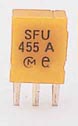
The ceramic componets are made of high stability piezoelectric ceramics that
functions as a mechanicalresonator. The frequency is primary adjusted by the
size and thikness of the ceramic element. Typical application includes TVs,
VCRs, telphones, remote controls and radios.
 What is the main purpose to have a ceramic
filter?
What is the main purpose to have a ceramic
filter?
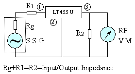
The filter is actually a bandpass filter with sharp filter characteristic. Figure
at right shows a test rig for a 455kHz ceramic filter. At the input you have
a signal generator and at the output you have RF voltmeter. The signal generator
will sweep the frequency from 400kHz to 500kHz. There is some resistor to impedance
match the filter.
Look now at the figure below wich shows the attenuation of the filter.
dB conversion?? Attenuation in dB = 20*log (attenuation in times)
Example: 100 time attenuation give 40dB attenuation because 40dB = 20 * log
(100)
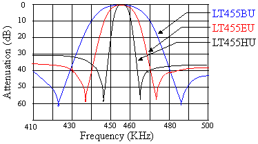 This diagram show attenuation versus the frequency for 3
different type of ceramic filters. If we start to look at 455kHz, we can see
that the attenuation is 0dB (no attenuation). Every signal wich is 455kHz will
pass through the filter witout any attenuation. If the frequency is more or
less than the 455kHz the attenuation increase. Look at the blue line. At 440kHz
and 470kHz the attenuation has reached 10dB (equal to 3.16 times). The output
signal (RF V.M) is only 31.6% of the input signal (S.S.G). The
red line is dropping faster and at 440kHz and 470kHz the attenuation has reached
40dB (equal to 100 times). The output signal is only 1/100 of the input signal.
The red ceramic filter is much sharper than the blue one.
This diagram show attenuation versus the frequency for 3
different type of ceramic filters. If we start to look at 455kHz, we can see
that the attenuation is 0dB (no attenuation). Every signal wich is 455kHz will
pass through the filter witout any attenuation. If the frequency is more or
less than the 455kHz the attenuation increase. Look at the blue line. At 440kHz
and 470kHz the attenuation has reached 10dB (equal to 3.16 times). The output
signal (RF V.M) is only 31.6% of the input signal (S.S.G). The
red line is dropping faster and at 440kHz and 470kHz the attenuation has reached
40dB (equal to 100 times). The output signal is only 1/100 of the input signal.
The red ceramic filter is much sharper than the blue one.
Bandwith
The definition of the BandWith of a ceramic filter is the frequency gap
where the signal has dropped less than 6dB.
The blue line has +/- 15kHz bandwith and the red line has +/- 6kHz bandwith.
The red line is sharper and dropps much faster.
There is filter with just a few kiloherts of bandwith. Lets say you have a FM-signal
where the IF is 455kHz. The main signal is 455kHz modulated with the audio signal.
Imagin the audio signal is +/- 20kHz then the total signal will be 455kHz +/-
10kHz. In such case you must use a wider filter to demodulate the total 20kHz.
If you use a sharper filter you will loose the 20kHz bandwith of sound.
The advantage of a sharper filter is that you will have less noise in the audio
signal.
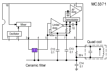
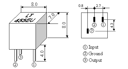
Practical use of ceramic filter in a receiver
This receiver is MC3371. Pin 16 is the RF input to the mixer and pin1 and pin2
is the local oscillator. The product comes out at pin 3. Imagin you want to
receive at 100MHz. The local oscillator is set to 100.455kHz and when the mixer
mix the RF (100MHz) with the osc (100.455MHz) the product will be 455kHz and
lots of other frequency products. What we want is only the 455kHz signal. And
it is here the ceramic filter comes handy. It filter away almost everything
except 455kHz +/- 10kHz.
The signal goes to pin 5 and limits and amplifyes. A FM-demodulator brings out
the sound from the 455kHz signal with the help of a quad coil. The audio
signal amplifyes and comes out at pin 9.
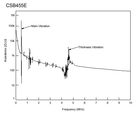
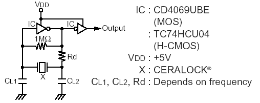
 Ceramic Resonators
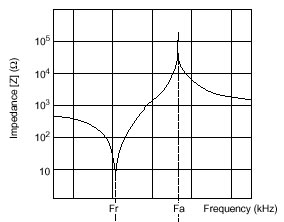 |
 |
![]()
[ About me
| Acronyms | CW
| Data Sheets | Docs
| Download | E-mail
| HOME | Ham
projects | Hobby circuits
| Photo galery | PIC
| QTH
photos |
Sign
in my guestbook | View
my guestbook ]
© 2001 - YO5OFH, Csaba Gajdos