|
HP-8640 Service: Hints & Kinks
|
Note:
None of the contributors or myself assume any liablility
for any damage caused by acting on information contained herein.
|
Most recent HINTS and KINKS Update is #28, March 13, 2023
If you have a hint or a solution for fixing the HP8640, especially if it
involves repairing or finding substitutes for HP parts that are no longer in
production please let us know and we will post it on this web page.
Service Hints
- HP8640B Frequency
display reads VFO directly (250-520MHz), 000.0->no osc.!
- If <250 MHz, VFO cuts out (esp. top of band) or O/P noisy, RF Divider U11/U12 area bad? >
- Normal VFO O/P
250-520MHz, about 0dBm with 0 to +2dB variation over band?
- VFO cavity repair is
extremely difficult (impossible?) without HP experience and tools.
- Aglient Technologies
(purchased HP) has online manual, see below.
- Sourcing? See HP
Part# to industry (JEDEC) #s PDF list
by (WA1GFZ) Frank Carcia.
|
Quick Links:
1. Output dies on tuning to high-end on all bands,
November 2004: Markus VE7CA
This may be due to a problem with the
128-256 MHz band ECL divider in RF Divider A10A2, the board located just
under the large die-cast cover on top-side of generator. If there is input at
the divider over the full freq. range but the output fails above a certain
freq. then this fix may apply.
A factory modification was made: 100 ohm variable resister R6 was added from
pin 13 of this divider to ground. This mod. increases the sensitivity of the
divider. To adjust the resister, tune gen. to high frequency end of band and
set resistor half-way between the high and low cutout. If the bias is too
high or low, the divider will not clock.
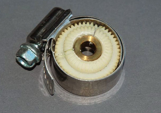
2. Cracked Wheels, November 2004: Hadley
K7MLR
I just
finished the first read of your article, quality work, thank you very much.
There are two other, very common, problems with the HP8640:
- The nylon
gears, in the gear trains, of the audio osc.
and range switch crack and will eventually fall apart. If caught in
time, epoxy will extend their life.
- The
small finger contacts, mounted to the clear Styrene wheels, located on
the range switch assembly and the attenuator will become intermittent.
Again with some work and epoxy this is pretty easy to fix. The Styrene
wheels are reversible and give new purchase points to re-mount the
fingers when they fall off. Every HP8640 I work on gets the epoxy treatment
on the wheels because the fault will occur sometime down the road. Just
a warning, don't lose any of the fingers during disassembly or you will
be up the creek unless you have a hanger queen.
Ed. Note: Picture of a Cracked Styrene Wheel on EB5ABV's
Web site is here. It shows a cracked wheel before
repair and the small finger contacts, mounted to a clear styrene wheel.
3. More Cracked Wheel Help, November 2004: Ken
VE3FIT ve3fit @ rac.ca
I read your article in QEX about repairing
an HP8640 and it led me to your web site. I greatly enjoyed both. Last
winter, I restored an 8640B which I had bought "as-is" on e-Bay.
Fortunately, it was a long winter: I did a repair on several cracked Delrin gears and in a nutshell, here it is:
- Having
removed the gear, I put it in a refrigerator's freezer compartment for a
few hours. This will cause the delrin to
shrink more than the brass hub. Drift out the brass hub. Mine came out
with just a gentle tap on a hammer and drift. (Credit the next part to
Jeff Liebermann). Use 24 hr epoxy to glue the Delrin back together. Use a round file to open up
the delrin centre
hole so that the brass hub will just fit back in. Epoxy the hub back in.
I had to replace the final power amp in my unit.
Fortunately, I managed to get a 'pull' from Fair Radio, but it cost about US
$125. I was just looking on the WJ Communications web site and it looks like
they now have several MMICs that could work in the 8640B. Check out their
ECG008.
It's great that you have offered your web
site for posting information regarding the HP8640.
4. Caution when storing HP8640, November
2004: Terry K7TAU
A retired co-worker (George Steen) has
located a fellow that worked at HP on the HP8640B RF generator and has been
corresponding with him regarding the instrument. Here is something George
passed along to me and suggested that I copy you on this information.
"Word of caution: don't store the
oscillators on-end (with their tuning shaft pointing up), because if you do
so, eventually the internal silicone grease migrates down to (and saturates)
the back plate where the transistor oscillator resides. The grease sometimes
gets between the plate and the case, causing loss of good electrical
connection. End result: the unit drops out of oscillation at parts of the
band - - or in bad cases, won't oscillate at any part of the band. "
This is a direct quote taken from correspondence between George Steen and
Greg Burnett, Retiree of HP.
Thought you might be interested in reading
this and perhaps posting this on your web page.
Regards, Terry K7TAU
5. Using a surface mount type MAV-11 and PCB,
December 2004: Angiolo Chiti I5SXN
I am I5SXN, an
old Italian radio amateur no more active but I am now only a technician. In
1999 I had the same problems on two generators HP8640B. At that time HP asked
me $600 for that modules. I solved the problems in the same way, as you, but
I opened the container of the amplifier and I introduced inside a small
printed circuit with an MMIC type MAV11, two condenser and a lot of chip
resistors series and parallel to obtain the right current for the MMIC and
dissipation using directly the 44 volt supply. I closed the container and in
this way if you open my HP8640 you do not see any transformation. I send You
the schematic diagram and the printed circuit indications.
PC
Board Layout & Schematic
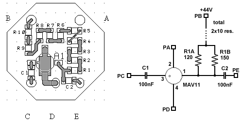
Printed circuit and mounting position of the components. The shape is
octagonal for problems with my CAD, I rounded the circuit before mounting in
the container. Diameter 25 mm. Distance between pins A and B 12.5 mm, and
between B and C 16.4 mm. The circuit was of 0.8 mm thickness, with copper on
the lower side. I scratched the copper around the active pins. With small holes
and wires I connected the ground pins of the MMIC to the lower copper side. I
used the original pins of the module. Another time I repaired the burned
final amplifier adding a zero bias diode on a different printed circuit. I
hope to be useful to you. Good luck and 73.
Angiolo Chiti I5SXN, E-mail: a.chiti @
rossbauer.it
6. Another replacement type for the MAV-11,
May 2005: Tom Bruhns K7ITM
I just photocopied a mixer article from QEX
(July/Aug 2004 issue) and happened to get the last page of an article you
apparently wrote about HP8640 amplifier issues. In footnote 4, you mentioned
a WJ amplifier. For a little better output power and quite a bit better IP3,
have a look at Sirenza SBF-5089. It's rated
nominally for 500MHz high end, but the rolloff is gradual
and it should be no problem using it in the 512MHz HP8640B. It's probably a
bit shy on power output to be used directly in the output stage if you need
full power output. The SBF-5089 has a particularly high IP3 (which is why I
know about it...), and you probably don't need that linearity in the 8640
output. For power output from a monolythic gain
block, have a look instead at the Sirenza SGA-7489,
which should give you a bit better IP3 than the WJ part and about twice the
output power--maybe enough to actually give full 8640 output. Plus, it's
rated for a wider frequency range.
Cheers, Tom Bruhns
7. Help for Oscillator Failure in the HP8640B.,
October 2005: John Klingelhoeffer WB4LNM
John wrote an excellant
article in the Sep/Oct 2005 issue of QEX describing how he fixed the
oscillator in his HP8640B generator. John describes in great detail the
process of disassembling the A3 oscillator assembly in order to get at the
oscillator circuit. He included many clear pictures of the inside of the generator
and oscillator assembly. If you don't have a copy of the QEX article you can
order a copy from ARRL.
8. Oscillator Frequency Adjustment HP8640B.,
January 2005: Markus VE7CA
If you set
your HP8640B so that the frequency counter reads exactly 10.000 Mhz but the output frequency is not exactly 10.000 Mhz, you can easily calibrate it yourself.
- Remove trim
strip that holds front panel window in place. Gently pull window up and
out and remove it. Allow generator to warm up for 2 hours.
- While
listening to WWV at say 10 MHz in a AM receiver,(with a a short length of wire attached to the generator
output), if your generator is off frequency even though the frequency
counter reads 10.000 Mhz, then you will hear a
beat note over-riding the WWV carrier. Adjust the time base adjustment
pot (available through the hole in the front of the counter casting)
until the oscillator is zero beat with WWV at 10 MHz, i.e. the beat note
disappears.
- Replace
front panel window and trim strip.
9. More Gear Information
for the HP8640B, March 2005: Jim
K8JL
In order to purchase new plastic gears for
the 8640B one must specify the Diametral pitch
(DP), the Pressure Angle, and of course, number of teeth, bore, thickness,
etc. The DP is 48. A new 20 deg. pressure gear does NOT mesh correctly with
the original gears. Hence, I conclude the pressure angle is 14.5 deg., the
other choice. I have not tried a new 14.5 gear with the originals, however. I
used Super Glue to mend split gears and it worked well. Clamp the pieces
together for a few hours. I could not pull the joint apart with my hands.
NOTE: The latest available manual from 1992 for the 8640B covers the
"new" assembly and it gives a detailed gear specification for the
combination gear:
"48-T 48-DP 14.5 DEG-PA".
Regards, and tnx for your help. Jim, K8JL.
10. More Information regarding Storing the HP8640,
January 2006: Jim Korenz N8PXW
Hi Markus:
I E-mailed you awhile back about HP8640B problems. I stored my 8640 face up.
When I read your webpages, I saw the comment bout intermittent frequency
operation. Sure enough, I had 7 dead sections in the tuning range, including
both ends. Additionally, the generator would not lock, even after an hour warmup.
I E-mailed Terry, K7TAU, for help. He recommended operating the unit face
down, to let the silicone grease flow back. After three months in this position,the HP8640 had only one dead spot in the middle
of the range and would lock. I turned the unit off and let itset flat for another couple of months. I turned it on
before Xmas, and lo and behold, the oscillator works perfectly. The bottom
line, you don't have o open the unit and dissemble and clean the cavity
oscillator to restore proper operation. You can let it sit face down, but it
will take some time to come back to full operation.
Thanks for your help, and your webpages.
11. Information regarding variable and fixed audio
irregularities in the HP8640, September 2006: Markus VE7CA
After finding and reading through the HP
repair information on your site, I thought the following may be of some
interest to fellow HP user's. My HP8640A developed a fault causing the
variable and fixed audio oscillator to stop working. I located the problem to
the thermistor module and discovered that the fault seemed to be an open
circuit between the common point (A) and the two series connected thermistors
to connection point (C). The path between (B) to (A) was ok. No information
is forthcoming in the HP manual regarding this component.
After trying several sources for a replacement and in most cases only being
offered a complete replacement board for £50 plus vat etc,
decided a cheaper cure must be sought. Trying various remedies I recalled
that a solution might be to use series connected lamps to replace the whole
original thermistor sealed assembly. I happened to have a supply of miniture 16v lamps so connected 3 in series and placed
them on the top of the pcb soldering directly to
the pads and interconnecting with thin wire.
The idea worked OK apart from a slight bouncing of the o/p amplitude at
switch on. The output remains stable otherwise. It may not be the best of
"fixes" but it cost nothing to achieve and will certainly suffice
for my needs.
Regards, Steve GW4ZDU
12. Information regarding manuals for the HP8640,
July 2007: Markus VE7CA
Aglient
Technologies who purchased HP has now posted operating and service manuals
for many of the older HP test equipment.
Click here to go direct to the HP8640 service manual site: HP8640
Manual.
13. Combination Gear Replacements, October 2007:
Markus VE7CA
One of the problems that many owners of the
HP8640 series signal generators face is finding a replacement for the
combination gears (( "Fig. 8-97, A9 Peak Deviation and Range Switch
Assembly" it is called: Item Number 13 and 19 (they are identical!),
Reference Designator A9MP12 and MP13, Description: Combination gear. ))
Recently I recieved an email from Mr. Wieschhoff in France regarding the Split Gear Combination
Assembly:
"After having followed the conversation of some interested circles in
early 2007 about the re-manufacture of the combination gears in the HP
generator 8640B I tried to get some information about the follow-up and
result. The early generators manufactured containing what I would call the
"old" dev./freq. switch assembly. The difference to the
"new" one is that it uses standard type switch segments where as
the "new" ones uses a printed circuit type rotary whiper discs to switch. Apparently both assemblies were manufactuerd in parallel for some time, since the manual
from 1976 covering the generator version HP8640A shows still the
"old" assy. The latest available manual from 1992 for the 8640B
surely covers the "new" assembly and for the fist time I see it
gives a detailed gear specification for the combination gear: "48-T
48-DP 14.5 DEG-PA". It may also have been given in manuals between 1976
and 1992 but I do not have any. In ALL manuals quoted (including the one
covering the "old" version) the part numbers for these gears are
identical: 1430-0773 and 1430-0774. In fact both different numbers describe
identical parts. Why HP did this I do no know but it may have been for
internal procedural reasons. I used a 0734 replacement gear bought from HP
some years ago (unfortunately at the time I only bought one) in place shown
for the 0774: no problems."
Best regards, Reinhart
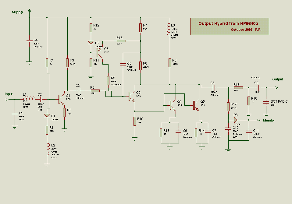
14. Final Hybrid Amplifier Replair, November 2008: Markus VE7CA
I recently
made a small SMD board to plug in in place of a blown output hybrid in a
8640B. I used the Philips BGA6589 and could reach about +6dBm. Whilst this
got the machine back in working order it was not as linear when modulated
really only got to 0dBm.
I started to wonder why the hybrid had died since it showed output on the
meter but none at the output pin. I concluded the either the output C had
become detached or it’s bond wire to the output pin broken. So I mounted the
hybrid on a hardwood mandrel and centred it in the
lathe and gently turned off the top.
Fig
6. Final Hybrid Amp. with lid removed.
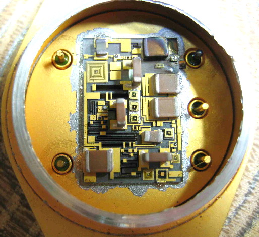
As the picture shows the bond wire to the output was vaporised!
The output C had a slight coating of gold sputter but was otherwise OK. A
small semiconductor pad capacitor which had been bonded to earth had also
melted and was undoubtedly the path to earth for the blast of volts which
took out the hybrid.
I soldered on to the output pin an 0805 50V 0.1 and connected it to the
original output C with a single strand of 0.2mm. The added capacitor is
because the old output C has now 10K of leakage. I re-inserted it in the
8640B put a piece of cling film over it and all is back to normal.
Click Here to view a copy of the circuit for the
final Hybrid Amplifier.
"The schematic attached is an educated guess at the hybrid by looking
closely at the blown up photo. The resistor values are scaled by measuring
the square area of a couple of known resistor values and applying this to the
other resistor tracks. Capacitors are estimated. The inductors are
calculated. This excellent job was done by Richard, G3SHK who made this sort
of stuff in a past-life at Philips labs".
I am pretty certain a good number of old output hybrid may have been zapped
by working on valve kit as the DC input voltage of the spec is very low. If
anyone has hung onto the hybrid I recommend peering inside! Mine had a
sapphire substrate but since you might encounter Beryllium Oxide turn at low
speed with care and wear a face mask!
73 Robin G3LBA
15. Various: Display - Lock Range - Split Gears,
January 2009: Mark Kolber WB2WHC
Mark has kindly provided details of
several remedies that he performed to his ailing HP8640B in (.doc) format. #1
describes how he fixed his display, +5 Volt supply and added a coupling capacitor
to the EXT input of the the counter to it is AC
coupled. (Mark used one 0.001 uF coupling cap. I
would suggest using two 0.001 uF capacitors in
parallel). #2 details how Mark increased the Lock Range. #3 talks about the
split gear situation common to the HP8640B.
#1 Display+ #2 Lock
Range #3 Split Gears
16. -5.2V Supply - No RF - Counter, January 2009:
Johan KC7WW
Johan described solutions to several
problems he inherited after he purchased a HP8640B.
Click to view KC7WW's article.
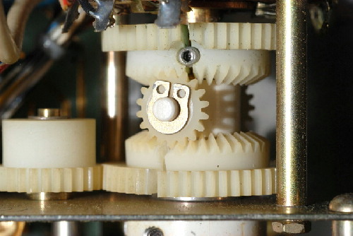
17. Frequency Tuning Gears, January 2009: Markus
VE7CA
Recently I
noticed that when turning the main frequency tuning dial I reached a point
where I began to feel resistance and if I continued to turn the dial further
I heard a loud click. This did not sound good so I decided to investigate.
After removing the bottom cover from the HP8640B, the first thing I noticed was
that some of the range assembly gears were cracked.
Fig
5. Split Gears in my HP8640B Combination Gear Assembly
Following the directions on Page 7-71 of the manual I removed the Switch
Assembly. Don't forget to take lots of pictures so that you can refer to them
again when putting everything back together. You need two different sized allen wrenches, a 1/16" (inch) and a 0.050" to
remove the knobs. I found that the set screws in the knobs were very tight
and my cheap set of allen wrenches stripped so I
had to purchase a high quality set.
Referring to page 7-70 in the HP8640B manual, gear numbers 13 and 14 were the
two effected gears. Do not remove the two small gears (which mesh with gear
#13 and #14) from shaft numbered #12. When you take the front gear off,
remove the whole shaft (#12) by gently pulling it out. Remember these gears
are very old and there are no replacements readily available. You can then
remove the rear gear #14.
The gears have cracked apart at the weakest point where the set screws go
through to the brass centre hub. The gears have
shrunk for some reason so they can not simply be glued back together because
the brass centre didn't scrink
along with the delrin gears.
Fig
6. Here my delrin gears after dis-assembly
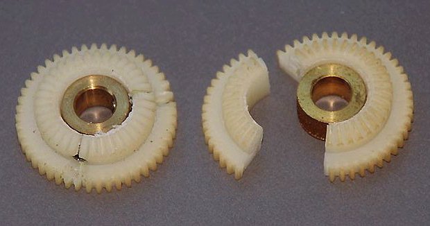
Using a file I carefully filed the centre of the delrin gears so that when replaced over the centre brass hub, the two pieces met. Leave enough room
for the glue and the delrin gears centre rough so that the glue has something to adhere
too. I strongly advise taking your time so you get it right the first time!
It is also necessary to enlarge the hole around the set screw with a small
file. This is really important. If you don't make the wholes large enough,
when you try to put the set screw back in, the set screw will pry the delrin gear apart again! Check it once and once again
before gluing.<BR
I was not able to find any 24 hour epoxy however I did find 5 hours expoxy. In order to hold the gears together while the
glue sets I used a hose clamp. Be very careful that you don't tighten the
camp too much or you may crush the teeth! Make sure there is no glue between
the teeth and the gear is flush with the brass hub.
Fig
7. Hose clamp holding gear together while glue sets
I recommend that you leave the gears in the clamp for 24 hours before
removing them.
Now all you have to do is re-assemble the gear assembly following the
directions in the manual. Hopefully you have taken notes and photographs in
case you forgot some important detail!
17.(B) Fixing the snapping
sound.
On the left side of the main oscillator
cavity there are two pots (VT and FM Gain Compensation pots) with gears
attached that turn in conjunction with the main tuning dial. Being I had a probem with the gears binding I removed the oscillator
cavity to investigate and saw that the lower pot gear was split. Mark WB2WHC,
in Hints and Kinks #16, notes that he had a similar problem. The snapping
sound I heard occured when the gear driving the two
pots tried to jump over the gap in the gear that had split apart. After glueing the split gear together I re-assembled the gears
and as Mark suggested, set the two pot gears so they didn't mesh with the centre gear at the set screw positions. You can do this
because these pots do not turn a full 360 degrees. I also re-set the Cavity
oscillator "end stop postion" as per the
instruction on page 5-36 and 5-37, making sure that the VT and FM Gain
Compensation pots did not reach their stops first.
Since I had all the knobs off, I did a thorough cleaning of the knobs and
front panel. After re-assembling everything and setting the knobs to their
correct position I was happy that the Main Cavity Tuning Knob turned without
binding and the frequency display corresponded to the Range Switch setting. I
let the generator warm for 2 hours and then following the instructions in
Hints and Kinks #8 I calibrated the frequency read out. (See page 5-35 in the
manual for further details.)
18. HP8640 High Speed Divider, April 2009: Nevel N2GX
Nevel kindly
shared his solution to repairing his HP8640 High Speed Divider Circuits. This
is a very creative solution describing how Nevel subsituted presently available IC's for original HP parts
which are no longer available.
Click to view a PDF file of Nevel's article in PDF.
19. Learning something the hard way, September
2009: Jeff King ZL4AI
With my last HP8640B, I undertook the
careful file out and epoxy gluing of one of the Delrin
gears. I clamped the parts together with a spring type clamp. In a hurry,
wanting to speed up the gluing process, I decided to heat up the gear. I
figured about one minute in the microwave would not be too much.
BIG MISTAKE.
Basically the gear melted! The Delrin material
melts at very low temperatures.
DO NOT HEAT UP IN A MICROWAVE UNDER ANY CIRCUMSTANCES.
I hope this warning will prevent others from destroying their gears. Jeff
ZL4AI
20. My (opt 002) had a dead output amp.,
May 2013: John Antone VK3ZAF
My unit (opt 002) had a dead output amp
but luckily I found a replacement part on Ebay (1st
May 2013) the vendor has a few of these and they work fine, search under HP
Agilent 08640-67025. They are not the specified amp as the handbook calls up
8640-67002 but they have the same specs except they need Vcc
of +23V and +44V I chose a 90 resistor so that it would run on 30V. Info
attached is what I did and the outcome.
Installed in sub assembly A26A1 is the
08640-67025. Please note that this amplifier has Vcc
of +23v to +44v MAX, therefore it cannot be just plugged in or the 44.6V
supply will zap it!. At the back of sub assembly A26, is where feed thru
capacitors provide power to the components, the output amplifier and the
pre-amplifier, the original output amplifier 08640-67002 is powered by 44.6V
fed from the rightmost feed thru. Unsolder this connection and insert a 90
ohm 3 Watt resistor into the circuit. I chose two 47 ohm resistors connected
in series mounted on a bracket ( all components found in my junk box) I’m
sure a much more elegant solution could be effected! This powers the
Amplifier (0840-67025) with about 30 volts. When removing the old amp and
installing the new one pay attention to anti static installation techniques.
After, I tested all frequencies, Flatness
512Mhz to 1024 Mhz about 0.2 db
except at mid band where it rises to about 0.5 db
over a range of about 50 Mhhz. Lower bands is about
0.2-0.3 db. Phase noise and FM and AM modulation unaffected. Measurements
made with 8553B and 8555A
The 08640-67025 could be used to replace
output amplifier on standard version of the 8640A or B.
Cheers VK3ZAF, jantonel
@ bigpond.net.au
21. Jitter Problem., January, 2014: Bodo
DL2FCN
The signal of my generator jittered a bit,
so +/- 30 Hz, sometimes more, to be seen clearly in the waterfall display of
my SDR. The jitter was present in the unlocked and locked condition.
The reason was the relay contact of the reed relay K1 "FM enable"
on the FM shaper and PLL filter board.
So I took a miniature relay and glued it on the existing relay K1, the
contacts of the new relay just soldered in parallel to the contacts of relay
K1. It solved the problem.
Dont know what happened to the reed-relay contact,
normally the relay is sealed and made for low current/voltage signals.
Anyway, the jitter is gone and I am again happy with my old generator HB8640.
vy 73 de Bodo/DL2FCN
22. More Cracked wheel solutions, October 2015:
Dr. Ramkumar Ramaswamy, Bangalore,
India
The transparent rotors on the range/max
deviation assembly - the ones with the small fingers - also have two brown
buttons on each one that counter balance the force of the contacts. These
buttons slide into small holes on the rotor and are not glued into place. The
manual makes no mention of them. So when you remove the rotors, chances are
that these buttons will simply fall off and you will lose them. This is to be
taken care of while taking apart the range/deviation assembly.
Apart from that there are some fairly standard tips:
(i) Put the gears in the sun if you can - makes
epoxy set much faster - in 2 hours or so instead of overnight. Certainly
microwaving is silly and I am surprised someone actually tried it.
(ii) Wash the gears in isopropyl alcohol or acetone before gluing. Acetone
dissolves many plastic but NOT delrin. I used
acetone and swished the gear around. Even though one gear just had a crack
and had not come apart that is enough for the acetone to get in and clean it.
(iii) Let the overnight epoxy sit for an hour before you apply. It sets just
a bit and loses its viscosity so it does not spread around all over after
that. So if you have a crack through a tooth, you can and should apply the
epoxy to the tooth halves and then stick together, gently wiping away the
excess with a toothpick (pun?).
(iv) Place the gear and brass insert face down on a flat surface so that the
insert and gear face are level. Tap the insert a few times with your finger
to make sure it has made contact with the flat surface.
One more tip which I discovered unexpectedly at the end of a hard day's work
trying to open the set screws with a 0.05 allen hex
key made by Allen - the original - in vain. All 4 screws were so tight that
these ALLEN keys stripped each time. This problem seems to be universal. I
tried applying heat with a soldering iron to the screw, tried immersing
things in Liquid Wrench for 8 hours...nothing worked. I found a tip somewhere
on the web by a guy who recommended taking a 1/16 bit and filing it down to
0.05. I tried that as a last resort - took one of the standard-sized driver
"bits" with a 1/16 hex end, laid it flat and carefully filed each
side till it started fitting into the 0.05 hole. Then I tapped it into the
hole gently with a plier so as to get a snug fit, and presto - it worked and
all 4 opened with just a finger twist.
23. Frequency Lock Problems., June 2016:
Dr. Jim K N8PXW
My HP8640 Problems:
I noticed in your trouble shooting tips that all zeroes on the display means
no cavity oscillator. That is partly true. In my case a low -5.2V power
supply, about -1.5V, caused all zeroes. It turns out that both cavity buffer
amps use the -5.2V supply, and a low voltage output will cause no oscillator
output.
Here is my story. From day one my unit had frequency lock problems. Even
after an hour warmup, I would lose lock after a couple of minutes. This was
frustrating to say the least, but I thought that it was normal. This year I
talked to a person in Dayton who fixes HP8640's and he said they should stay
locked for hours after warmup. After returning home I did some checks. The
manual says the unit should say in lock for 1/4 turn of the fine tuning
control, and drop out by 3/4 turn. OK, mine says in lock for 1/2 turn in each
direction. So that's not my problem. I let the unit warmup overnight. Next
morning my display read all zeroes. After removing the top cover, I noticed
that the -5.2V led was glowing weakly. As I watched, it got dimmer and dimmer
till it went out. OK, regulator board problem. The ua723 regulator chip
drives a 2N3053 which drives a 2N3055 pass transistor. I replaced the 2N3053,
same problem. Replaced what I thought was the 2N3055, same problem. OK it
must be the 723, the local shop had an NTE replacement a NTE923 in the ten
pin can for $9. I replaced the part, powered up, and everything came back to
life. I then let the unit run overnight. Next morning, all zeroes.
Now I'm stumped. The local shop had only one part. I found a parts dealer 50
mi away and made the trip the next day. This time I double checked
everything. I assumed the pass transistor was on the rear heat sink cooled by
the fan. Wrong! I traced the wires on the motherboard to a transistor mounted
on a flange on the bottom on the chasis, accessable after removing the bottom cover. I replaced
the 723, the 2N3053, the only thing left was the pass transistor, 2N3055.
When I tried to remove the part, it wouldn't release from the chasis. I finally pried it free with a screwdriver. Apparently,
someone had replaced it before, but instead of using silicone grease,
thermally conductive, he used silicone rubber, a thermal insulator. I
replaced that transistor. I then checked the other power transistors on the
rear heatsink. One was also silicone rubbered, but
the others were dry, and needed new grease. After regreasing
the above, I measured the transistor's temps, the coolest was 98 deg, the warmest 108 deg, a
little warm, but you could keep your finger on the case. I then ran the
HP8640 all night, and in the morning everything was good and the freq still locked.
Bottom line, if the last signal generators were made in 1991, the latest
models are 25 years old and the pass transistors should be checked. My
problems apparently stemmed from the pass transistor over heating and
eventually causing the 723 regulator to fail.
24. Divide by 64 IC problem in RF Scaler Assembly,
June, 2017: Bodo DL2FCN
Suddenly my HP8640B counter displayed
irregular and ilogical frequencies. In the
beginning I thought that something was wrong with the range selector,
fortunately this was not the case. A short test with my spectrum analyser confirmed a clean signal within the selected
ranges.
The external input of the frequency counter, in range 0-10MHz, was ok but from
10-512MHz the was irregular. So I got the impression that something within
the RF Scaler Assembly must be defective. The problem was the U1 divide by 2.
This IC divided irregularly, not by 2. N2GX faced a problem with U1 and
replaced it bwith a modern IC, an MC100EL31D single
D type flip-flop. See repair report No. 18 here in VE7CA’s hint and kinks.
I thought it might be better to replace the complete divide by 64 chain with
an IC, preferably a DIL 8 type. So I found the U664BS, used in TV sets for the
VHF/UHF Tuner PLL. This IC divides up to 1,1GHz, the output signal is ECL
level, no problem to integrate it into the existing circuit. You can see on
the attached photo, that the new IC socket was soldered into the holes of the
defective IC U1. I had just to cut the connection to the old divider chain
and to solder small wires to the new divider by 64 IC. A nice side effect is,
that the new IC draws less current, so the heat in the shielded compartment
is less in respect to the old, now disconnected IC’s.
The modification works fine, except that the IC is self-oscillating if
missing input signal. This is in internal mode. No problem since the cavity
oscillator is delivering a steady signal. In external counter mode, this
behavior is not really disturbing, you just have to know it.
Here in Germany you can easily find the IC U664BS (Box 73 in Berlin). Other
IC’s are MB501L, MC12079D or U891, which I couldn’t test, of course!
SV1AFN is selling dividers, see 'https://www.sv1afn.com/shop.html' in prescalers.
25. HP8640B Frequency divider fix, December
2018: Timo Hyvönen OH7LMQ
Once I got this generator, the 256-512
(512-1024 too, I have the doubler option installed)
range worked normally. When I switched any of the lower ranges, for example
128-256, the generator had bizarre behaviour. When
the frequency dial was in its most clockwise position, the output was good
(highest freq.). After turning some 2,5 to 3 revs ccw,
the output suddenly dropped and slowly started to rise again. An external
frequency counter was then connected to output. It locked 2xf out compared to
internal counter. Because internal counter has it's own divider and input
from cavity oscillator, it was soon suspected that divider assy is the culprit. After checking this with spectrum
analyzer, it was soon discovered that the main signal collapsed and the
second harmonic was the highest output. The unit's power out meter showed
this sudden output decrease too.
So, I took off divider assy top cover and then I
could measure the chips. I didn't have this fast oscilloscope, so I connected
the spec.analyzer via 100p cap into u12 output
(pin6), which is the first range divider. Loss of output was discovered.
Because this is the first divider in the chain, the same failure will be
present all the ranges below.
At this point comes along N2GX's fix for the counter problem divider fix
No:18 in this site. The first and second dividers are the same HP propietary / obsolete (and very fragile) chip. Marked as
1820-0736. I could not obtain the MC100EL31D anywhere, but farnell had MC10EL31DG, which is similar. Because this is
a small IC, I ordered an adaptor also (RE932-01 - Adaptor, SMD farnell code:1426169) and soldered the IC in this first.
After removing the original IC, a piece of teflon
tape was used to prevent any short circuits. And the adaptor was placed upon
the tape. This adapter was bit too wide, and it was effectively masking
the IC holes. With a small file , I shaved couple of mm. off from the sides,
and it was perfect fit then. 1N914 was subsituted
with 1N4148 and the 270R resistors, I was out of them, but 330R seems to work
fine. Otherwise I followed the original article. After this the circuit board
was installed back, and all the screws. Perfect operation was confirmed.
Fig
8. Mod. View
26. HP8640B no lock using
x10 function. 2.Att. switch at -145dbm,
December 2018: Federico IZ5EBO
1. I have my first HP8640B in
awhile. It had a problem: nice loop working in normal mode, but unable to
lock using the X10 function. After some head scratching, I've found the
culprit: it was a leakage in A8A2C17 (0.47uF 25VL), see attached photos. I
suggest to change all orange capacitors in A8A2 board, and elsewhere if you
find others.
2. Another little bug on my 8640B. After playing with it, I realized
that the LAST (-145dBm) attenuator step was never engaged. Like there was a
STOP. Wondering if it was switch trouble, I dared to dismantle it. Well, to
make a long story short, see photo. There is a mechanical stop inside the
attenuator, using a metallic "pin" on the cam. This pin was too
much outside from it's original position, rubbing on the die-cast, stopping
the switch just before the last position. I pressed it inside the cam,
restoring the original position. Now all the attenuator steps are engaged :-)
Hope this will help others 8640B fans. 73 de IZ5EBO Federico
Fig
9. Mod. View
27. HP8640B Counter not
Locking. , March 4th and 8th,
2020: Jemp, ON7MA
Just repaired a HP8640 Counter Unit
1. It did not lock at all and this was due to the the
fact that 4-8Mhz was entering the counter print, but did not reach the Phase
comparator U26A en U26B
After investigating, it seemed that Counter Load did not get any pulses…
Investigating the signal flow, I found the culprit, U17B did not continue the
signal anymore.. after changing this everything worked fine… !
2. One of my HP8640'B took a long time warming up to reach lock?
I Investigated further and found a new thermal sensitive chip in the time
base print A8. A3 U9 was very thermal sensitive.. when it was warm it worked,
and when cold it did not..
I changed this chip 74LS290 and now it locks from almost zero start…
Off course, it is always best to lock freq after
some warm up time.. say about 5 min or so…
Jemp, ON7MA Belgium
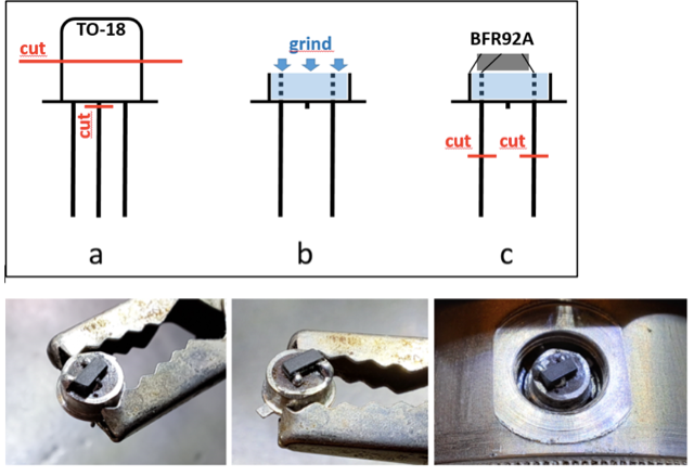
28. DK5KF's Osc Replacement , March 13, 2023: Thomas, DK5KF
Shortly I
noticed a ´dead spot´ on all bands of my HP8640B (no output, counter zero),
suggesting a RF oscillator problem. I replaced transistor A3Q1 with one from
a good 8640B and the problem was gone.
Hence I needed a replacement transistor, but did not find an appropriate
equivalent. After some experimentation I came out with the following solution:
I took a 2N2222 in TO-18 case and cut the middle lead (base). Then the top
half of the TO-18 case was cut away with a diamond wheel (sketch, a). Next,
the transistor
interior was grinded down to the ceramic layer surrounding the wires (sketch,
b). I selected a BFR92A (SOT23, fT=5 GHz, noise
figure=2.1 dB), which was connected
to the prepared rest of the TO-18 case (sketch, c). The BFR92A was mounted
top down and the solder tags bent down to align the connections as needed.
Finally,
the two legs of the TO-18 case (collector and emitter) were shortened as
needed to fit into the RF oscillator socket. Minimal remains of solder were
removed from the outside to fit the ´new´ transistor in the screw cap. The
metal mesh in the cap was removed. The transistor was inserted into the
socket
and the cap screwed in very carefully. The whole work was a bit of
microsurgery, requiring a magnifying lamp, fine pincette,
SMD soldering iron and a steady hand.
See the photos below.
Fig
10. Mod. View
With this homemade transistor the RF oscillator works perfectly. Upper and
lower band limits are quite the same and harmonic distortion unchanged
(generator set to 400 MHz: first harmonic 53dB down).
No higher harmonics or nonharmonic products detectable. Warm-up drift was
unchanged. FM modulation level was slightly increased (about 10%), which can
be corrected by adjustment of FM sensitivity.
Thomas, DK5KF
If you have any solutions for problems you have encountered for the
HP8640 series signal generators, please let us know at: 
|
