|
HP-8640 Service: My Story
|
Note:
I assume no liablility for any damage caused by
acting on information contained herein.
|
For additional information regarding repairs to the HP8640
series generator see "Hints and Kinks" page
|
The
HP8640 signal generator, though out of production for many years, is still
a real jewel when it comes to HF/VHF signal generators. It is a very rugged
instrument with a wide frequency range (0.5 MHz to 500Mhz), with RF output
depending upon model number between 16 dBm to
over 20 dBm and a built in attenuator that
attenuates the RF down to -140 dBm accurate to
within + or - 0.5 db. I obtained a used HP8640B in 2002 and it worked
flawlessly until one day the output became intermittent. This led me down
the path of looking for the problem and finding a solution. The problem was
the pre-amp. hybrid amplifier. Since this part is no longer in production I
decided to try and replace it with a three terminal power amplifier, the
MAV-11. The solution was described in my article in QEX July/August.
Here is an abbreviated version of Help For The HP8640
By Markus Hansen, VE7CA
If you own a HP8640 signal generator and the output power has become
intermittent or it has quit working all together, then read on.
|
1. Locating The Problem
On the back of the generator is a large heat sink and extending from the heat
sink is a BNC connector marked Aux. Output. Connect a scope or a RF power
meter to the BNC connector and turn the generator on. If there is no output
at this point, the problem is either the hybrid pre-amp., the supply voltage
for the pre-amp. or any of the circuits preceding the pre-amp. If there is no
RF at the BNC outlet, turn the generator up side down and remove the bottom
cover. Turn the generator so the back is facing you and remove the cover from
the AM/AGC AMPLIFIER ASSY which is located in the lower right hand corner.
This assembly is divided into two sections, the A26A3 Modulator Assy. is on
the left side (which contains the pre-amp. hybrid) and the A26A1 Power
Amplifier and AGC Detector Assy. on the right side.
In each section you will see what looks like a large power transistor in a
case style similar to a TO-3 or TO-8 transistor. The hybrid amplifiers are
contained under the caps of these units. On the PC board, in the left
section, locate the end of the 50 ohm coax line with the center connector
terminating in a circuit pad. (see Fig. 1)
Fig 1. A26A3 Modulator Assy
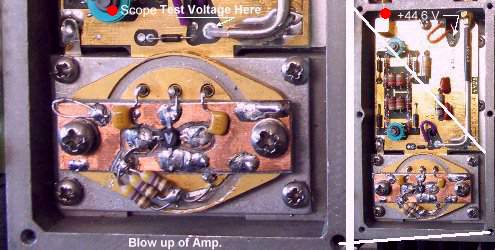
Turn the frequency range switch of the generator to its lowest range and turn
the generator on. With a scope determine if there is any RF at the end of the
50 ohm coax. If there is, and it is a square wave measuring 550 mVp-p, then you have confirmed that everything before the
pre-amp is working and the problem is either the pre-amp or the power supply.
The only way to really find out if it is one or the other is to remove the
pre-amp. hybrid by removing the two screws holding it in place. Once the
pre-amp. is removed check the supply voltage that it is +44.6 volts. The
+44.6 volt input is clearly marked on the PC. If there is no voltage present
or it is the wrong value then proceed to fix the power supply problem. The
reason that you have to remove the pre-amp. to check the voltage is that the
pre-amp. may have an internal short, which was the case with my pre-amp. The
power supply has what is called a crow-bar shut down feature, where if the
output is shorted, the voltage goes to zero preventing damage to the power
supply.
2. Changing Supply Voltage For The MAV-11
The MAV-11 requires 5.5 Volts while the hybrid amplifiers both run on 44.6
Volts. The 44.6 V line enters the AM/AMPLIFIER ASSY box that contains both
amplifiers via a multiple pin connector and then along a PC board trace in
the center of the box. There is no spare pin on the connector so a
feedthrough capacitor has to be added to bring in a voltage line for the
MAV-11.
With the back of the generator towards you, take off the top cover. The
AM/AGC AMPLIFIER ASSY is now located in the bottom left corner. Remove the
AM/AMPLIFIER ASSY from the generator by following the instructions on the
amplifier lid. Once removed, turn it so that the side opposite the hint sink
is facing up. There you will find a removable rectangular aluminum plate.
After you remove the screws and the plate you will see a row of feedthrough
capacitors in the cavity below. From one end there are two wires that go from
feedthrough capacitors to the section that contains the hybrid pre-amp. The second
wire (white with purple and brown bands) from the end is connected between
the feedthrough capacitor +44.6 volt input line and a pad on the pre-amp. PC
board that is marked 44.6 V. Unsolder this wire from the feedthrough
capacitor. Make a mark on the aluminum plate in the middle between the two
end feedthrough capacitors. Drill a hole to fit a feedthrough capacitor. I
used a good quality 0.001 uF feedthrough capacitor
that I had purchased from Down East Microwave. One end is threaded so that
when it is screwed into the aluminum plate the result is a very secure RF
connection. Connect the wire that was soldered to the +44.6 V feedthrough
insulator to the new feedthrough insulator using heat shrink tubing to cover
the solder connection. Connect a 12" length of insulated wire to the
outside of the new feedthrough insulator and again pass short length of
shrink tubing over the connection. See Fig 2. Now reassemble the AM/AMPLIFIER
ASSY and insert it back into the generator.
FIG 2.

The other end of the wire just attached to the outside of the new feedthrough
insulator is now soldered to a hole at the end of a trace that leads to C4
that is on the power supply rectifier assembly circuit board. I choose this
point as the voltage is approximately +15 volts leaving sufficient room to
drop the voltage to 5.5 volts for MAV-11 while limiting the current to 60 ma.
Also this particular winding has the largest current capability of all the
transformer windings. C4 is 8200 uF and large
enough that I was not able to detect any ripple on my scope.
3. Substituting A MAV-11 For The Hybrid Pre-Amp
I had some Mini-Circuits MAV-11 amps. on hand so I decided to try one as a
substitute for the pre-amp hybrid. You may want to choose another model such
as the MAV-11SM or ERA-1SM that has a typical gain flatness up to 2 GHz of
+/-0.5 dB., 0.02 dB better than the MAV-11, though
I don't think it will make much difference because the generator has an AGC
circuit to keep the output power at a constant output.
Begin by removing the cap from the existing pre-amp. module. I inserted the
module in a vise and using a metal punch I was able to get under the seal of
the cap and pry it up and off. I removed the hybrid from the base by tapping
the edge with a small screwdriver. I decided to use the original base of the
hybrid because it has the connecting posts that connect through to the PC
board below and it has room on top for a MAV-11 and associated parts. I cut a
small piece of PC board to fit between the connecting posts and extending
over the mounting holes of the base. If you use a MAV-11 then drill a hole in
the center of the PC board large enough so that the MAV-11 drops into place
and the four leads lie on top of the PC board. I used a Dremel
tool to cut isolation pads for the input and output pins of the MAV-11.
Facing the back of the generator and looking at the base that holds the
hybrid pre-amp., the connecting posts farthest away from the back of the
generator from left to right are: output, ground and input. The connecting
posts closest to the back are the left post (not used) and the right post,
(voltage supply input). From the base input post connect a 4 dB pad in series
with a 0.1uF monolithic or surface mount capacitor. The other end of the
capacitor goes to the input pin of the MAV-11. Between the voltage supply
input post on the base and the output pin of the MAV-11 connect three 470 ohm
1/4 w resistors in parallel. The three parallel resistors should measure
about 157 ohms and serve to drop the supply voltage from 15 volts to approx.
5.5 volts and limit the current to 60 ma. From the output pin of the MAV-11
connect another 0.1 uF monolithic or surface mount
capacitor to the output post of the base. See Fig 3. for the schematic.
FIG 3. Schematic

Before putting the AM/AGC AMPLIFIER ASSY cover back on, make sure that the
new components do not touch the lid of the cover. I cut a small single sided
PC board to cover the MAV-11 and new components and soldered the copper side
of the PC board to the screen that is sandwiched between the cover and the
assembly box. It took me several hours to perform the above changes. I
strongly recommend that you do not hurry when making the suggested changes.
You don't want to make a mistake that may cause other problems that are not
fixable because of the scarcity of some of the HP original parts.
4. Summary
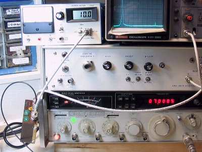
When I completed the substitution and turned on the generator, with the
attenuator set to 0 dBm, the generator output meter
read 0 dBm and my RF power meter connected to the
output connector also registered 0 dBm. This was
with the frequency set to 875 kHz. I was one very happy person. According to
my RF power meter the output is within +/- 0.2 dB across the generators full
operating frequency range. (I had previously calibrated the RF Power Meter
using the signal generator as the source and confirmed the calibration using
another HP8640 that a friend owns.) The repaired generator also produces full
power across the full frequency range of the generator, which for the HP8640
Avionic Version is +13dBm. The AM and FM modulation features of the generator
were not affected by the substitution.
FIG 4. HP8640 with Power
Meter
Obviously, the problem outlined in this article is only one of many reasons
why a HP8640 series signal generator may not be working. However, it became
clear after discussions with a number of fellows hams that had years of
experience working with this particular series of generators that the hybrid
pre-amp is prone to failure. Hopefully this article will help those who
experience a similar problem. It is interesting to note that there is a
notation on the circuit diagram for the Avionic Version of the HP8640
indicating that the output amplifier is a 16 dBm
amplifier. The MAV-11 may therefore also work as a substitute for the final
amplifier hybrid. This would not be the case for other versions of the HP8640
as they typically have a higher output power than the Avionic Version that
has a max. output power of 13 dBm. The MAV-11 is
listed as having a max. output power of 18 dBm (1 db Comp. Typ). If it was used
to replace the final power amplifier in the higher power generators, then the
AGC circuit will not be effective unless it is adjusted to recognize that the
new amplifier is only capable of putting out 18 dBm
max. There may be three terminal amplifiers available that provide more than
18 dBm that would be a better substitute for the
final amplifiers in the higher output generators.
I have not been able to confirm this, but I was told that the last year that
the HP hybrids were being produced they sold for over $200 US. I paid $2.65
US for the MAV-11's when I purchased them a couple of years ago. Now that is
progress!
|