|
630m Band Exploration
Latest Updates:
April 11, 2019: A serious amplifier for 630 Meters.
July 2018: New. QST (Pg. 36) An Antenna for 630 to 10 Meters
March 2017. My 630 M Transverter.
June 17, 2016: 630 Transverter.
Author: Hansen, Markus, VE7CA
Encouraged by my friend Steve, VE7SL in June 2016 I built a tranmitter for the new amateur radio band, 630 Meters
(475 KHz). Check Steve's blog for further inforatiom
about local BC activity on 630 meters: ve7sl.blogspot.ca/
For my first 630 Meter transmitter I used GW3EUP's design . Here is his URL,
http://www.gw3uep.ukfsn.org/472kHz.htm
The vfo and amplifier was composed of two parallel
IRF510's run in class D followed by a low pass filter. At +12 Volts it put
out 14 watts.
March 2017. A 630M TRANSVERTER:
. In order to be able to use the digital modes like WSPR, JT8 etc, I decided to build a transverter
to convert the 10 MHz band of my TEN-TEC Omni VI+ to the LF band. The Omni VI
does not have a low power output connection so that was the first thing I had
to do. Since I use a separate antenna for receive, the output from the
transceiver converter is connected directly to the Omni VI auxillary antenna input jack. Using a small signal relay
I interrupted the transmit signal just before the Omni VI power amplifier to
bring the transmit output to a PL259 connector which drives the transmitter
portion of the 630 M transverter.
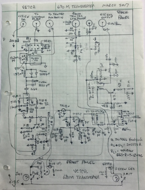
Here is a hand drawn diagram of the circuit that I used.
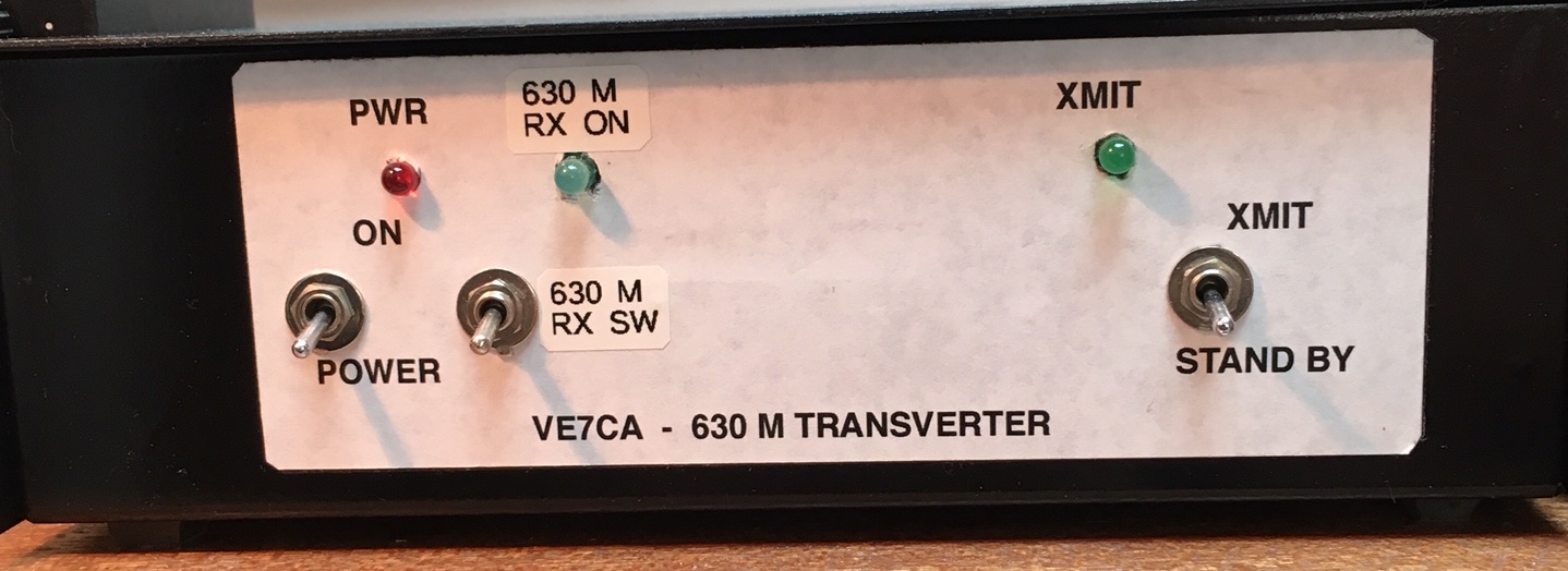
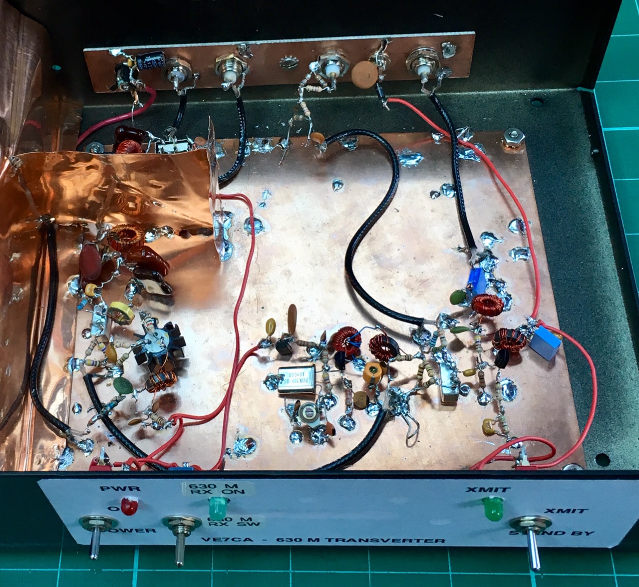
The following picture shows the front panel and the following picture the
inside of the transvert showing just the
transmitter portion. The 630M receive converter is located inside the copper
shielded encloser.
630m 100-225 WATT POWER AMPLIFIER
To increase power ouput to the legal limit of 5
Watts ERP a higher power amplifier was needed. I decided to replicate
WB4JWM's design. He used two IRFP250 MOSFET's in parallel in Class D to
produce 100 watts ouput with a 24 volt supply. By
increasing the supply voltage to 36 volts the IRFP250's will safely produce
225 watts. What I like about this circuit is it includes a SWR Shut-Down
circuit if the antenna SWR exceeds a preset amount. You can find WB4JWM's
description and circuit at NJDTechnologies Web
site:
http://njdtechnologies.net/wb4jwm-630-meter-non-linear-amplifier/
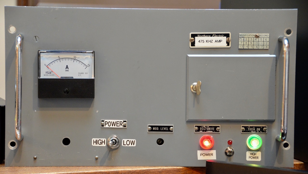
Here is a photo of the amplifier housed in a repurposed old AM transmitter
enclosure I found in my attic.
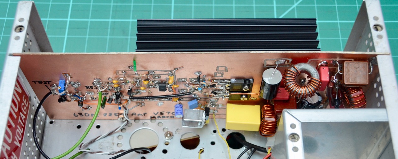
The next photo is looking inside the amplifier and reveals the PC board that
I built the SWR shut down circuit and the MOSFET amplifier on. With a 24 Volt
supply to the MOSFETs and terminated in a 50 ohm dummy load I measured the
output power at 132 watts which equates to 87.2% efficiency. All harmonices are -58dB or more below the carrier level.
As previously noted one feature of Tom's circuit is a SWR Shut Down feature.
This circuit will shut the MOSFETs off if the antenna SWR exceeds a preset
number, say 1.5:1 or 2:1. MOSFET'S do not handle avalanche breakdown caused
by reactive loads. In other words as an RF amplifier they like to work into a
low SWR antenna, in this case 50 ohmns. If you turn
the transmitter on and you mistakenly do not have the transmitter connected
to the antenna, or your antenna comes disconnected or falls down you will
blow the MOSFET's. Believe me, I have! So, this Shut Down circuit is a big
benefit.
I did not have a BF244A for Q1. A J310 did not work as I could not lower the
source standby voltage to 0.62 volts without drawing excess current. A MPF102
worked with the source resistor at 830 ohms. Tom, the author of the circuit
indicated that the 27 ohm resistors in series with the diodes that are
attached to the gates of the MOSFET's can be reduced in value or elliminated if the MOSFET's do not not
completely shut down when you engage the Test button. Instead of the BAT46's
series diodes I used IN5819's as they can safely handle more current if
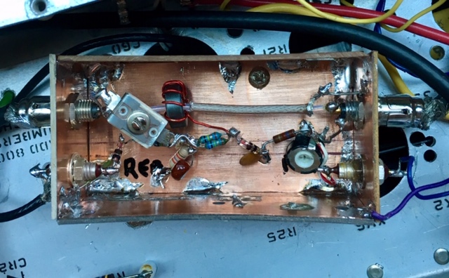
needed. The SWR unit is mounted in the bottom of the repurposed chassic as seen in the following photo. I used phono
connectors for the input and output connections so that I could reverse the
SWR coupler to null the reflected power to zero with C1 when connected to a
50 ohmn load.
73 VE7CA
|